Dell Latitude CPt V Service Manual - Page 24
Release the keyboard from the palmrest assembly by inserting a small
 |
View all Dell Latitude CPt V manuals
Add to My Manuals
Save this manual to your list of manuals |
Page 24 highlights
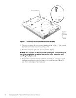
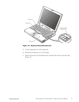
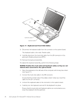
10-mm screws (7) M2.5x10 2. Remove the seven 10-mm screws, labeled with a "circle K," that secure the keyboard to the computer (see Figure 9). 3. Turn the computer right-side up and open the display. 4. Release the keyboard from the palmrest assembly by inserting a small flat-blade screwdriver under the edge of the blank key (see Figure 10), and lift the right edge of the keyboard. 16 Dell Latitude CPt V-Series/CPx H-Series Service Manual
-
 1
1 -
2
-
3
-
4
-
5
-
6
-
7
-
8
-
9
-
10
-
11
-
12
-
13
-
14
-
15
-
16
-
17
-
18
-
 19
19 -
 20
20 -
 21
21 -
 22
22 -
 23
23 -
 24
24 -
 25
25 -
 26
26 -
 27
27 -
 28
28 -
 29
29 -
30
-
31
-
32
-
33
-
34
-
35
-
36
-
37
-
38
-
39
-
40
-
41
-
42
-
43
-
44
-
45
-
46
 |
 |
16
Dell Latitude CPt V-Series/CPx H-Series Service Manual
±²³´µ¶·5¹··Ê¶¼»Ë²À³·¾&¶·6¶ÅÈ»Áµ!·ÆÇǶ¼ÈÉÅ·Íε¶ÏÇ
2.
Remove the seven 10-mm screws, labeled with a
“
circle K,
”
that secure
the keyboard to the computer (see Figure 9).
3.
Turn the computer right-side up and open the display.
±²³´µ¶·¸³ÂÀ¸&À˽¾ÄÁ¸Å»¸¿ÂÀ¸&ÀËΞü¸¾ÃÀ¸ÊþȺÆÀ"¸À¾ÁºÆ˸¼ºÁÆżÈÀ¼"¸
¾»¼¸¿ºÇÀ%½Å»ÁÌǺ»È¸¿Å¸ÃÀÄƾ½Àϸ4À¸½¾ÃÀÊÌƸÉÂÀ»¸ÃÀÇÅͺ»È¸¾»¼¸
¾»¼Æº»È¸¿ÂÀ¸&ÀËΞüÏ
4.
Release the keyboard from the palmrest assembly by inserting a small
flat-blade screwdriver under the edge of the blank key (see Figure 10),
and lift the right edge of the keyboard.
10-mm screws (7)
M2.5x10