Dell Latitude CPt V Service Manual - Page 42
see
 |
View all Dell Latitude CPt V manuals
Add to My Manuals
Save this manual to your list of manuals |
Page 42 highlights
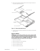
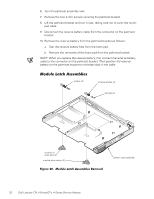
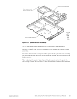
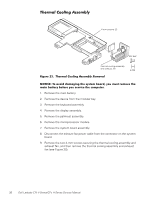
diskette that provides a utility for transferring the service tag number to the replacement system board assembly. 1. Remove the main battery. 2. Remove the device from the modular bay. 3. Remove the keyboard assembly. 4. Remove the display assembly. 5. Remove the palmrest assembly. 6. Remove the microprocessor module. 7. Remove any PC Cards or plastic blanks from the PC Card slot. 8. Verify that the PC Card ejectors do not extend from the PC Card slot. 9. Remove the following two screws from the system board assembly (see Figure 19): The 4-mm screw with captive washer located on the far left side of the computer between the hard-disk drive assembly and the PC Card slot. The 4-mm screw with captive washer located on the far right side of the computer in front of the TCA and to the right of the microprocessor module. NOTE: Locate these screws by looking for the white circles on the system board that outline the captive washers. 34 Dell Latitude CPt V-Series/CPx H-Series Service Manual
-
 1
1 -
2
-
3
-
4
-
5
-
6
-
7
-
8
-
9
-
10
-
11
-
12
-
13
-
14
-
15
-
16
-
17
-
18
-
19
-
20
-
21
-
22
-
23
-
24
-
25
-
26
-
27
-
28
-
29
-
30
-
31
-
32
-
33
-
34
-
35
-
36
-
 37
37 -
 38
38 -
 39
39 -
 40
40 -
 41
41 -
 42
42 -
 43
43 -
 44
44 -
 45
45 -
 46
46
 |
 |
