Dell Latitude CPt V Service Manual - Page 38
These screws, labeled with
 |
View all Dell Latitude CPt V manuals
Add to My Manuals
Save this manual to your list of manuals |
Page 38 highlights
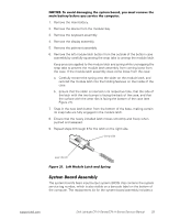
20-mm screws (5) M2.5x20 1. Remove the main battery. 2. Remove the device from the modular bay. 3. Remove the keyboard. 4. Remove the display assembly. 5. Turn the computer upside down on a flat work surface. 6. Remove the five 20-mm screws that secure the palmrest to the computer. These screws, labeled with a "circle P," are located underneath the front edge of the computer (see Figure 18). 7. Turn the computer right-side up on the work surface. 30 Dell Latitude CPt V-Series/CPx H-Series Service Manual
-
 1
1 -
2
-
3
-
4
-
5
-
6
-
7
-
8
-
9
-
10
-
11
-
12
-
13
-
14
-
15
-
16
-
17
-
18
-
19
-
20
-
21
-
22
-
23
-
24
-
25
-
26
-
27
-
28
-
29
-
30
-
31
-
32
-
 33
33 -
 34
34 -
 35
35 -
 36
36 -
 37
37 -
 38
38 -
 39
39 -
 40
40 -
 41
41 -
 42
42 -
 43
43 -
44
-
45
-
46
 |
 |

30
Dell Latitude CPt V-Series/CPx H-Series Service Manual
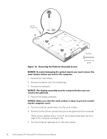
±²³´µ¶·¸4¹··Ê¶¼»Ë²À³·¾&¶·$Áɼµ¶Ç¾·ÆÇǶ¼ÈÉÅ·Íε¶ÏÇ
±²³´µ¶·¸³Å¸¾Íź¼¸¼¾Ç¾Èº»È¸¿ÂÀ¸ÁËÁ¿ÀǸΞü"¸ËÅ̸ÇÌÁ¿¸ÃÀÇÅÍÀ¸¿ÂÀ¸
Ǿº»¸Î¾¿¿ÀÃ˸ÎÀÊÅÃÀ¸ËÅ̸ÁÀÃͺ½À¸¿ÂÀ¸½ÅÇÄÌ¿ÀÃÏ
1.
Remove the main battery.
2.
Remove the device from the modular bay.
3.
Remove the keyboard.
±²³´µ¶·¸³ÂÀ¸¼ºÁÄƾ˸¾ÁÁÀÇÎÆ˸ÇÌÁ¿¸ÎÀ¸ÃÀÇÅÍÀ¼¸ÎÀÊÅÃÀ¸ËÅ̸½¾»¸
ÃÀÇÅÍÀ¸¿ÂÀ¸Ä¾ÆÇÃÀÁ¿Ï
4.
Remove the display assembly.
±²³´µ¶·¸,¾&À¸ÁÌÃÀ¸¿Â¾¿¸¿ÂÀ¸ÉÅÃ&¸ÁÌÃʾ½À¸ºÁ¸½ÆÀ¾»¸¿Å¸ÄÃÀÍÀ»¿¸Á½Ã¾¿½Â%
º»È¸¿ÂÀ¸½ÅÇÄÌ¿Àø½ÅÍÀÃÏ
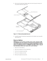
5.
Turn the computer upside down on a flat work surface.
6.
Remove the five 20-mm screws that secure the palmrest to the computer.
These screws, labeled with a
“
circle P
,
”
are located underneath the front
edge of the computer (see Figure 18).
7.
Turn the computer right-side up on the work surface.
20-mm
screws (5)
M2.5x20