Dell Latitude CPt V Service Manual - Page 37
Reinstall the four 5-mm screws to secure the LCD panel to the top cover.
 |
View all Dell Latitude CPt V manuals
Add to My Manuals
Save this manual to your list of manuals |
Page 37 highlights
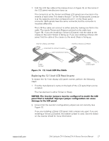
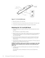
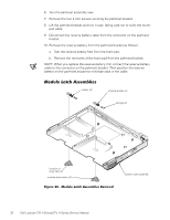
Do not force the LCD flex cable into the connector. If you have trouble, check to make sure the LCD flex cable is folded correctly and try again. 6. Lay the LCD panel in the top cover. 7. Connect the two-wire back-light plug to the connector on the inverter. When the plug is all the way in the connector, the key slot in the center of the plug should not be visible. If you can see the key slot, the plug is not in the connector correctly. Pull the plug out, turn the plug over, and reinsert it into the connector. 8. Reinstall the four 5-mm screws to secure the LCD panel to the top cover. 1. Remove the display assembly bezel. 2. Remove the LCD panel. 3. Remove the display assembly latch by unsnapping the latch and captive spring from the inside of the display assembly top-cover assembly (see Figure 14). The palmrest assembly consists of the touch pad and the palmrest. support.dell.com Dell Latitude CPt V-Series/CPx H-Series Service Manual 29
-
 1
1 -
2
-
3
-
4
-
5
-
6
-
7
-
8
-
9
-
10
-
11
-
12
-
13
-
14
-
15
-
16
-
17
-
18
-
19
-
20
-
21
-
22
-
23
-
24
-
25
-
26
-
27
-
28
-
29
-
30
-
31
-
 32
32 -
 33
33 -
 34
34 -
 35
35 -
 36
36 -
 37
37 -
 38
38 -
 39
39 -
 40
40 -
 41
41 -
 42
42 -
43
-
44
-
45
-
46
 |
 |
