Dell Latitude CPt V Service Manual - Page 44
Disconnect the exhaust-fan power cable from the connector on the system
 |
View all Dell Latitude CPt V manuals
Add to My Manuals
Save this manual to your list of manuals |
Page 44 highlights
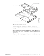
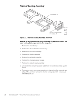
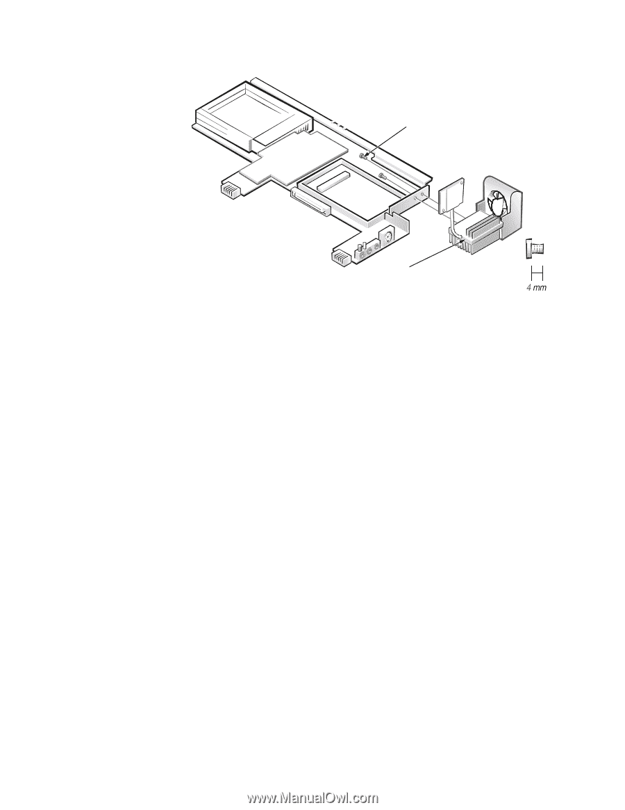
4-mm screws (2) M2.5x4 thermal cooling assembly and exhaust fan 1. Remove the main battery. 2. Remove the device from the modular bay. 3. Remove the keyboard assembly. 4. Remove the display assembly. 5. Remove the palmrest assembly. 6. Remove the microprocessor module. 7. Remove the system board assembly. 8. Disconnect the exhaust-fan power cable from the connector on the system board. 9. Remove the two 4-mm screws securing the thermal cooling assembly and exhaust fan, and then remove the thermal cooling assembly and exhaust fan (see Figure 20). 36 Dell Latitude CPt V-Series/CPx H-Series Service Manual
-
 1
1 -
2
-
3
-
4
-
5
-
6
-
7
-
8
-
9
-
10
-
11
-
12
-
13
-
14
-
15
-
16
-
17
-
18
-
19
-
20
-
21
-
22
-
23
-
24
-
25
-
26
-
27
-
28
-
29
-
30
-
31
-
32
-
33
-
34
-
35
-
36
-
37
-
38
-
 39
39 -
 40
40 -
 41
41 -
 42
42 -
 43
43 -
 44
44 -
 45
45 -
 46
46
 |
 |
36
Dell Latitude CPt V-Series/CPx H-Series Service Manual
$,¼³¾²ÀºÊÃÃÀ·+.º½¸¸¼¾¿ÀÁº
±²³´µ¶·Â̹··#&¶µ¼ÁÉ·º»»É²À³·ÆÇǶ¼ÈÉŷʶ¼»ËÁÉ
±²³´µ¶·¸³Å¸¾Íź¼¸¼¾Ç¾Èº»È¸¿ÂÀ¸ÁËÁ¿ÀǸΞü"¸ËÅ̸ÇÌÁ¿¸ÃÀÇÅÍÀ¸¿ÂÀ¸
Ǿº»¸Î¾¿¿ÀÃ˸ÎÀÊÅÃÀ¸ËÅ̸ÁÀÃͺ½À¸¿ÂÀ¸½ÅÇÄÌ¿ÀÃÏ
1.
Remove the main battery.
2.
Remove the device from the modular bay.
3.
Remove the keyboard assembly.
4.
Remove the display assembly.
5.
Remove the palmrest assembly.
6.
Remove the microprocessor module.
7.
Remove the system board assembly.
8.
Disconnect the exhaust-fan power cable from the connector on the system
board.
9.
Remove the two 4-mm screws securing the thermal cooling assembly and
exhaust fan, and then remove the thermal cooling assembly and exhaust
fan (see Figure 20).
4-mm screws (2)
thermal cooling assembly
and exhaust fan
M2.5x4