Dell Latitude CPt V Service Manual - Page 29
Remove the three 4-mm screws, labeled with
 |
View all Dell Latitude CPt V manuals
Add to My Manuals
Save this manual to your list of manuals |
Page 29 highlights
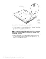
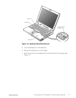
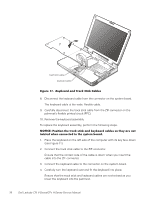
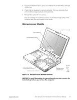
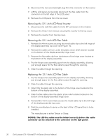
display assembly hinge cover LCD flex cable snap tab bottom case assembly 4-mm screws (3) snap tab M2.5x4 1. Remove the keyboard. 2. Close the display. 3. Remove the three 4-mm screws, labeled with a "circle D," from the back of the computer (see Figure 13). 4. Open the display. 5. Disconnect the LCD flex cable from the connector on the system board by pulling the connector straight up. support.dell.com Dell Latitude CPt V-Series/CPx H-Series Service Manual 21
-
 1
1 -
2
-
3
-
4
-
5
-
6
-
7
-
8
-
9
-
10
-
11
-
12
-
13
-
14
-
15
-
16
-
17
-
18
-
19
-
20
-
21
-
22
-
23
-
 24
24 -
 25
25 -
 26
26 -
 27
27 -
 28
28 -
 29
29 -
 30
30 -
 31
31 -
 32
32 -
 33
33 -
 34
34 -
35
-
36
-
37
-
38
-
39
-
40
-
41
-
42
-
43
-
44
-
45
-
46
 |
 |

support.dell.com
Dell Latitude CPt V-Series/CPx H-Series Service Manual
21
¶·¸ÏÀ²Áº½¸¸¼¾¿ÀÁº
±²³´µ¶·¸Ì¹··)²Ç½ÉÁÅ·ÆÇǶ¼ÈÉÅ
±²³´µ¶·¸³Å¸¾Íź¼¸¼¾Ç¾Èº»È¸¿ÂÀ¸ÁËÁ¿ÀǸΞü"¸¿ÂÀ¸ÄÅÉÀø½¾ÎÆÀ"¸Î¾¿%
¿ÀÃË"¸¾»¼¸ÁÀ½Å»¼¸Î¾¿¿ÀÃ˸(ºÊ¸º»Á¿¾ÆÆÀ¼*¸ÇÌÁ¿¸ÎÀ¸ÃÀÇÅÍÀ¼¸ÎÀÊÅÃÀ¸ËÅ̸
ÁÀÃͺ½À¸¿ÂÀ¸½ÅÇÄÌ¿ÀÃÏ
±²³´µ¶·¸2Ÿ»Å¿¸ÃÀÇÅÍÀ¸¿ÂÀ¸Ä¾ÆÇÃÀÁ¿¸ÎÀÊÅÃÀ¸ËÅ̸ÃÀÇÅÍÀ¸¿ÂÀ¸¼ºÁÄƾËÏ
1.
Remove the keyboard.
2.
Close the display.
3.
Remove the three 4-mm screws, labeled with a
“
circle D,
”
from the back
of the computer (see Figure 13).
4.
Open the display.
5.
Disconnect the LCD flex cable from the connector on the system board by
pulling the connector straight up.
4-mm screws (3)
LCD flex cable
display assembly
bottom case assembly
hinge cover
M2.5x4
snap tab
snap tab