Dell Latitude CPt V Service Manual - Page 33
Remove the display assembly bezel.
 |
View all Dell Latitude CPt V manuals
Add to My Manuals
Save this manual to your list of manuals |
Page 33 highlights
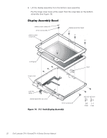
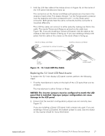
rubber screw covers (4) 4-mm screws (6) plastic screw covers (2) display assembly bezel 5-mm screws (4) LCD panel LCD flex cable display-assembly top cover back-light plug latch inverter ZIF connector 3-mm screws (3) M3.0x3 M2.5x4 M3.0x5 To remove the 12.1-inch display LCD panel, perform the following steps: 1. Remove the main battery. 2. Remove the keyboard. 3. Remove the display assembly. 4. Remove the display assembly bezel. 5. Remove the four 5-mm screws securing the LCD panel to the top cover. support.dell.com Dell Latitude CPt V-Series/CPx H-Series Service Manual 25
-
 1
1 -
2
-
3
-
4
-
5
-
6
-
7
-
8
-
9
-
10
-
11
-
12
-
13
-
14
-
15
-
16
-
17
-
18
-
19
-
20
-
21
-
22
-
23
-
24
-
25
-
26
-
27
-
 28
28 -
 29
29 -
 30
30 -
 31
31 -
 32
32 -
 33
33 -
 34
34 -
 35
35 -
 36
36 -
 37
37 -
 38
38 -
39
-
40
-
41
-
42
-
43
-
44
-
45
-
46
 |
 |

support.dell.com
Dell Latitude CPt V-Series/CPx H-Series Service Manual
25
!")!µ*+Æ,º¶·¸ÏÀ²Áº°Ê¶º-²+¼Àº
±²³´µ¶·¸*¹··¸Â¹¸1°ÀÎ&·)²Ç½ÉÁÅ·ÆÇǶ¼ÈÉÅ
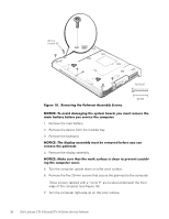
To remove the 12.1-inch display LCD panel, perform the following steps:
1.
Remove the main battery.
2.
Remove the keyboard.
3.
Remove the display assembly.
4.
Remove the display assembly bezel.
5.
Remove the four 5-mm screws securing the LCD panel to the top cover.
4-mm screws (6)
rubber screw covers (4)
plastic screw
covers (2)
latch
LCD panel
display-assembly top cover
LCD flex
cable
inverter
back-light
plug
5-mm screws (4)
3-mm screws (3)
display assembly bezel
M3.0x3
M2.5x4
M3.0x5
ZIF
connector