Dell Latitude CPt V Service Manual - Page 31
Remove the display assembly.
 |
View all Dell Latitude CPt V manuals
Add to My Manuals
Save this manual to your list of manuals |
Page 31 highlights
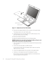
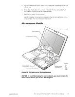
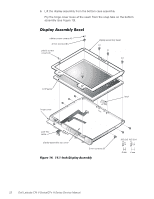
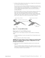
1. Use a scribe to carefully pry the four rubber screw covers out of the four screw holes located at the top of the bezel on the front of the display assembly. 2. Remove the four 4-mm screws located at the top of the bezel on the front of the display assembly (see Figure 14). 3. Use a scribe to carefully pry the two plastic screw covers out of the two screw holes located at the bottom of the bezel on the front of the display assembly. 4. Remove the two 4-mm screws from the bottom of the bezel. 5. Separate the bezel from the display-assembly top cover. The bezel is secured by three tabs on the left and right side of the displayassembly top cover. 1. Remove the main battery. 2. Remove the keyboard. 3. Remove the display assembly. 4. Remove the display assembly bezel. 5. Remove the three 3-mm screws on the left side of the LCD panel and the three 3-mm screws on the right side of the LCD panel (see Figure 14). 6. Lift and rotate the top of the LCD panel out of the top cover. Disconnect the ZIF connector and the display-assembly interface cable connector (see Figure 4). 7. Lift the LCD panel out of the top cover. NOTES: Remove and replace the LCD panel as a complete assembly. Use a magnetic screwdriver to reassemble the LCD panel in the display. Secure the right side first. support.dell.com Dell Latitude CPt V-Series/CPx H-Series Service Manual 23
-
 1
1 -
2
-
3
-
4
-
5
-
6
-
7
-
8
-
9
-
10
-
11
-
12
-
13
-
14
-
15
-
16
-
17
-
18
-
19
-
20
-
21
-
22
-
23
-
24
-
25
-
 26
26 -
 27
27 -
 28
28 -
 29
29 -
 30
30 -
 31
31 -
 32
32 -
 33
33 -
 34
34 -
 35
35 -
 36
36 -
37
-
38
-
39
-
40
-
41
-
42
-
43
-
44
-
45
-
46
 |
 |
