Dell Latitude CPt V Service Manual - Page 43
display screen.
 |
View all Dell Latitude CPt V manuals
Add to My Manuals
Save this manual to your list of manuals |
Page 43 highlights
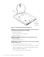
4-mm screws with captive washers (2) system board assembly bottom case assembly M2.5x4 10. Lift the system board assembly out of the bottom case assembly. Be sure to transfer the memory module(s) to the replacement system board assembly. Insert the diskette that accompanied the replacement system board assembly into the diskette drive, and turn on the computer. Follow the instructions on the display screen. After replacing the system board assembly, be sure to enter the system's service tag number into the BIOS of the replacement system board assembly. support.dell.com Dell Latitude CPt V-Series/CPx H-Series Service Manual 35
-
 1
1 -
2
-
3
-
4
-
5
-
6
-
7
-
8
-
9
-
10
-
11
-
12
-
13
-
14
-
15
-
16
-
17
-
18
-
19
-
20
-
21
-
22
-
23
-
24
-
25
-
26
-
27
-
28
-
29
-
30
-
31
-
32
-
33
-
34
-
35
-
36
-
37
-
 38
38 -
 39
39 -
 40
40 -
 41
41 -
 42
42 -
 43
43 -
 44
44 -
 45
45 -
 46
46
 |
 |

support.dell.com
Dell Latitude CPt V-Series/CPx H-Series Service Manual
35
±²³´µ¶·Â¹··ÍÅǾ¶¼·Ä»Áµ!·ÆÇǶ¼ÈÉÅ
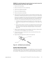
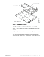
10. Lift the system board assembly out of the bottom case assembly.
Be sure to transfer the memory module(s) to the replacement system board
assembly.
Insert the diskette that accompanied the replacement system board assembly
into the diskette drive, and turn on the computer. Follow the instructions on the
display screen.
After replacing the system board assembly, be sure to enter the system
’
s
service tag number into the BIOS of the replacement system board assembly.
4-mm screws with
captive washers (2)
system board assembly
bottom case assembly
M2.5x4