Dell Latitude CPt V Service Manual - Page 6
Screw Placement Mat With Component Screw Counts - memory
 |
View all Dell Latitude CPt V manuals
Add to My Manuals
Save this manual to your list of manuals |
Page 6 highlights
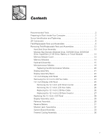
Figure 1. Figure 2. Figure 3. Figure 4. Figure 5. Figure 6. Figure 7. Figure 8. Figure 9. Figure 10. Figure 11. Figure 12. Figure 13. Figure 14. Figure 15. Figure 16. Figure 17. Figure 18. Figure 19. Figure 20. Figure 21. Figure 22. Figure 23. Computer Orientation 1 Main Battery Assembly Removal 3 Screw Identification 3 Disconnecting an Interface Cable 5 Exploded View-Computer 12 Hard-Disk Drive Assembly Removal 13 Modular Bay Device Removal 13 Memory Module Removal 14 Removing the Keyboard Assembly Screws 16 Keyboard Assembly Removal 17 Keyboard and Track Stick Cables 18 Microprocessor Module Removal 19 Display Assembly 21 14.1-Inch Display Assembly 22 12.1-Inch Display Assembly 25 12.1-Inch LCD Flex Cable 27 12.1-Inch LCD Inverter 28 Removing the Palmrest Assembly Screws 30 Palmrest Assembly Removal 31 Module Latch Assemblies Removal 32 Left Module Latch and Spring 33 System Board Assembly 35 Thermal Cooling Assembly Removal 36 Table 1. Table 2. Screw Placement Mat With Component Screw Counts and Sizes 4 Parts and Assemblies 6 vi
-
 1
1 -
 2
2 -
 3
3 -
 4
4 -
 5
5 -
 6
6 -
 7
7 -
 8
8 -
 9
9 -
 10
10 -
 11
11 -
 12
12 -
13
-
14
-
15
-
16
-
17
-
18
-
19
-
20
-
21
-
22
-
23
-
24
-
25
-
26
-
27
-
28
-
29
-
30
-
31
-
32
-
33
-
34
-
35
-
36
-
37
-
38
-
39
-
40
-
41
-
42
-
43
-
44
-
45
-
46
 |
 |
