Dell Latitude CPt V Service Manual - Page 28

same height. If one or more corners of the module are higher than the others

Page 28 highlights

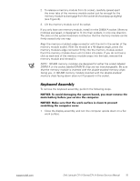
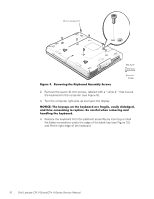
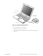
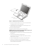
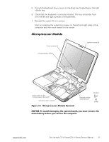
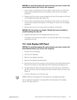
1. Remove the main battery. 2. Remove the keyboard assembly. 3. Remove the two 3-mm screws on the microprocessor shield that secure the thermal cooling assembly to the microprocessor module (see Figure 12). 4. Loosen the three captive screws securing the microprocessor shield to the microprocessor module. 5. Remove the microprocessor shield. 6. Rotate the arm of the thermal cooling assembly up and away from the microprocessor module. 7. Use a microprocessor extractor tool to remove the microprocessor module. The tool fits on the left side of the module aligned with white marks on the front and back edge of the processor board (see Figure 12). When you reinstall the microprocessor module in the system board, make sure that you align the microprocessor connector on the left side of the board and press down firmly on the metal plate that is directly over the connector. When the microprocessor module is seated, all four corners must be at the same height. If one or more corners of the module are higher than the others, the module is not seated correctly. Pay attention to the corner without the mounting screw. If necessary, apply pressure directly over this corner to ensure the module is fully seated. Rotate the arm of the thermal cooling assembly into place and replace the microprocessor shield. Replace the two 3-mm screws that secure the thermal cooling assembly arm and shield to the microprocessor module. Tighten the three captive screws on the corners of the shield to secure the microprocessor module and shield. 20 Dell Latitude CPt V-Series/CPx H-Series Service Manual

  • 1
  • 2
  • 3
  • 4
  • 5
  • 6
  • 7
  • 8
  • 9
  • 10
  • 11
  • 12
  • 13
  • 14
  • 15
  • 16
  • 17
  • 18
  • 19
  • 20
  • 21
  • 22
  • 23
  • 24
  • 25
  • 26
  • 27
  • 28
  • 29
  • 30
  • 31
  • 32
  • 33
  • 34
  • 35
  • 36
  • 37
  • 38
  • 39
  • 40
  • 41
  • 42
  • 43
  • 44
  • 45
  • 46

20
Dell Latitude CPt V-Series/CPx H-Series Service Manual
1.
Remove the main battery.
2.
Remove the keyboard assembly.
±²³´µ¶·¸³Å¸À»ÁÌÃÀ¸Ç¾6ºÇÌǸ½ÅÅƺ»È¸ÊÅø¿ÂÀ¸Çº½ÃÅÄÃŽÀÁÁÅÃ"¸¼Å¸»Å¿¸
¿Å̽¸¿ÂÀ¸ÂÀ¾¿¸¿Ã¾»ÁÊÀø¾ÃÀ¾Á¸Å»¸¿ÂÀ¸¿ÂÀÃǾƸ½ÅÅƺ»È¸¾ÁÁÀÇÎÆ˸(³µ¹*ϸ
³ÂÀ¸ÅºÆÁ¸º»¸ËÅÌøÁ&º»¸ÃÀ¼Ì½À¸¿ÂÀ¸ÂÀ¾¿¸¿Ã¾»ÁÊÀø½¾Ä¾ÎºÆº¿Ë¸Åʸ¿ÂÀ¸
¿ÂÀÃǾƸľ¼Áϸ
3.
Remove the two 3-mm screws on the microprocessor shield that secure
the thermal cooling assembly to the microprocessor module (see
Figure 12).
4.
Loosen the three captive screws securing the microprocessor shield to the
microprocessor module.
5.
Remove the microprocessor shield.
6.
Rotate the arm of the thermal cooling assembly up and away from the
microprocessor module.
±²³´µ¶·¸-ÂÀ»¸ÃÀÇÅͺ»È¸¿ÂÀ¸Çº½ÃÅÄÃŽÀÁÁÅøÇżÌÆÀ"¸ÄÌÆƸ¿ÂÀ¸Çż%
ÌÆÀ¸Á¿Ã¾ºÈ¿¸ÌÄϸ2Ÿ»Å¿¸ÇÅÍÀ¸¿ÂÀ¸¿ÅÅƸÊÃÅǸÁº¼À¸¿Å¸Áº¼À¸¿Å¸À6¿Ã¾½¿¸¿ÂÀ¸
ÄÃŽÀÁÁÅøΞüÏ
7.
Use a microprocessor extractor tool to remove the microprocessor
module.
The tool fits on the left side of the module aligned with white marks on the
front and back edge of the processor board (see Figure 12).
±²³´µ¶·¸¹º»¼²º½·¶¾¿³¾¿¶²ÀÀ¿¾º½¿Á´²
±²³´µ¶·¸5ÃÅÄÀøÁÀ¾¿º»È¸Åʸ¿ÂÀ¸Çº½ÃÅÄÃŽÀÁÁÅøÇżÌÆÀ¸ÃÀ0̺ÃÀÁ¸¾¸
½Å»Áº¼ÀþÎÆÀ¸¾ÇÅÌ»¿¸ÅʸÊÅýÀ¸(¾ÄÄÃÅ6ºÇ¾¿ÀÆ˸78¸ÄÅÌ»¼Á¸9:;¸&ºÆÅ%
ÈþÇÁ<*¸¾ÄÄƺÀ¼¸¾ÎÅÍÀ¸¿ÂÀ¸ÇżÌÆÀ¸½Å»»À½¿ÅÃϸ¹¸Çº½ÃÅÄÃŽÀÁÁÅø
ÇżÌÆÀ¸¿Â¾¿¸ºÁ¸»Å¿¸ÄÃÅÄÀÃÆ˸ÁÀ¾¿À¼¸½¾»¸ÃÀÁÌÆ¿¸º»¸¾»¸º»¿ÀÃǺ¿¿À»¿¸½Å»%
»À½¿ºÅ»¸¾»¼¸ÁÌÎÁÀ0ÌÀ»¿¸Ê¾ºÆÌÃÀÁϸ
When you reinstall the microprocessor module in the system board, make
sure that you align the microprocessor connector on the left side of the board
and press down firmly on the metal plate that is directly over the connector.
When the microprocessor module is seated, all four corners must be at the
same height. If one or more corners of the module are higher than the others,
the module is not seated correctly.
Pay attention to the corner without the mounting screw. If necessary, apply
pressure directly over this corner to ensure the module is fully seated.
Rotate the arm of the thermal cooling assembly into place and replace the
microprocessor shield. Replace the two 3-mm screws that secure the thermal
cooling assembly arm and shield to the microprocessor module. Tighten the
three captive screws on the corners of the shield to secure the
microprocessor module and shield.