Dell Latitude CPt V Service Manual - Page 32
of the display assembly.
 |
View all Dell Latitude CPt V manuals
Add to My Manuals
Save this manual to your list of manuals |
Page 32 highlights
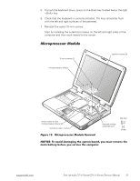
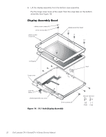
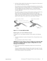
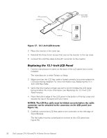
1. Remove the 4-mm screw securing the metal cable clip to the left hinge of the display-assembly top cover (see Figure 14). 2. Remove the cable out from under the plastic strain relief retainer located on the bottom of the display-assembly hinge cover. 3. Remove the clip from the bottom of the hinge cover located at the bottom of the display assembly. 4. Pry the hinge-cover assembly apart from the display assembly, allowing just enough space for the flex cable to pass through the opening. Slide the cable through the opening. 24 Dell Latitude CPt V-Series/CPx H-Series Service Manual
-
 1
1 -
2
-
3
-
4
-
5
-
6
-
7
-
8
-
9
-
10
-
11
-
12
-
13
-
14
-
15
-
16
-
17
-
18
-
19
-
20
-
21
-
22
-
23
-
24
-
25
-
26
-
 27
27 -
 28
28 -
 29
29 -
 30
30 -
 31
31 -
 32
32 -
 33
33 -
 34
34 -
 35
35 -
 36
36 -
 37
37 -
38
-
39
-
40
-
41
-
42
-
43
-
44
-
45
-
46
 |
 |

24
Dell Latitude CPt V-Series/CPx H-Series Service Manual
˼¾Ã»·+.ºÈ,¼º!()!µ*+Æ,º°Ê¶º/À¼0ºÊ²¿À¼
1.
Remove the 4-mm screw securing the metal cable clip to the left hinge of
the display-assembly top cover (see Figure 14).
2.
Remove the cable out from under the plastic strain relief retainer located
on the bottom of the display-assembly hinge cover.
3.
Remove the clip from the bottom of the hinge cover located at the bottom
of the display assembly.
4.
Pry the hinge-cover assembly apart from the display assembly, allowing
just enough space for the flex cable to pass through the opening.
Slide the cable through the opening.