Dell OptiPlex GX200 Service Manual
Dell OptiPlex GX200 Manual
 |
View all Dell OptiPlex GX200 manuals
Add to My Manuals
Save this manual to your list of manuals |
Dell OptiPlex GX200 manual content summary:
- Dell OptiPlex GX200 | Service Manual - Page 1
Dell™ OptiPlex™ GX200 Service Manual Small Form-Factor Chassis - Removing and Replacing Parts Low-Profile Chassis - Removing and Replacing Parts Midsize Chassis - Removing and Replacing Parts Mini Tower Chassis - Removing and Replacing Parts Notes, Notices, and Cautions Throughout this guide, blocks - Dell OptiPlex GX200 | Service Manual - Page 2
Parts: Dell™ OptiPlex™ GX200 Systems Service Manual Overview Recommended Tools Precautionary Measures Internal Views Computer Cover Eject, Power, and Reset Buttons Front-Panel Inserts Control Panel Chassis Intrusion Switch Drives System Power Supply Expansion-Card Cage Riser Boards System Board - Dell OptiPlex GX200 | Service Manual - Page 3
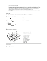
of the low-profile chassis to help you orient yourself when you work inside the computer. Figure 1. Low-Profile Chassis Orientation View 1 System board 2 Hard-disk drive 3 Power supply 4 Externally accessible drive bays Figure 2 shows the low-profile chassis with the cover removed. Figure 2. Inside - Dell OptiPlex GX200 | Service Manual - Page 4
place. To reset the chassis intrusion detector, perform the following steps: 1. Reconnect all cables to their connectors at the back of the computer. 2. Restart the system. 3. Enter System Setup. To do this, press when F2=Setup appears in the upper-right corner of the screen. If the operating - Dell OptiPlex GX200 | Service Manual - Page 5
: 1. Lay the computer cover on a flat work surface, with the inside of the top cover facing up. 2. To remove the 3.5-inch diskette-drive eject button, pull gently on the plastic part of the button until it comes free. 3. To remove the power button or the reset button, use a small screwdriver and - Dell OptiPlex GX200 | Service Manual - Page 6
panel in the low-profile chassis, perform the following steps: 1. Disconnect the control panel cable from the PANEL connector on the system board (see "System Board Labels" for the location of the PANEL connector). 2. From inside the chassis, remove the mounting screw that secures the control panel - Dell OptiPlex GX200 | Service Manual - Page 7
the front of the computer. Figure 9. Drive Locations 1 5.25-inch drive 2 3.5-inch diskette drive 3 Hard-disk drive 4 Chassis intrusion switch NOTE: Computer configurations differ. Your computer may have an Iomega Zip drive installed instead of a 3.5-inch diskette drive, or your computer may have no - Dell OptiPlex GX200 | Service Manual - Page 8
drive to verify that it is configured for your computer system. 2. If not already done, remove the computer cover. 3. To install the hard-disk drive to the bracket, place the drive with a screw. 7. Connect a power cable to the power input connector on the back of the drive (see Figure 12). 8. Check - Dell OptiPlex GX200 | Service Manual - Page 9
on the hard-disk drive. For instructions, refer to the documentation that came with your operating system. System Power Supply Figure 13. Power Supply Removal 1 AC power cord 2 AC power receptacle 3 Power supply 4 DC power cables 5 Securing screw To remove the system power supply, perform the - Dell OptiPlex GX200 | Service Manual - Page 10
from the system board and drives. It is important to route these cables properly when you replace them to prevent them from being pinched or crimped. 3. Remove the screw below the fan guard on the back of the chassis. 4. Slide the power supply toward the front of the computer approximately 1 inch - Dell OptiPlex GX200 | Service Manual - Page 11
of the computer. 1. Remove the expansion-card cage. 2. Remove the expansion cards installed in the slots. 3. Remove the screws securing the riser board to the expansion-card cage. 4. Lift the riser board off the expansion-card cage. System Board Components Figure 17 shows the system board and the - Dell OptiPlex GX200 | Service Manual - Page 12
sockets (2) 12 DC power 1 connector 13 DC power 2 connector 14 Chassis intrusion connector 15 Control panel connector 16 External speaker connector 17 EIDE1 connector 18 EIDE2 connector 19 System board speaker 20 System board jumpers 21 Diskette/tape-drive connector 22 Riser board connector 23 Real - Dell OptiPlex GX200 | Service Manual - Page 13
fan connector Hard-disk drive LED connector EIDE interface connector Chassis intrusion switch connector Keyboard connector Modem audio connector Video connector Mouse connector Control panel connector Parallel port connector; sometimes referred to as LPT1 PCI expansion-card connector Main power - Dell OptiPlex GX200 | Service Manual - Page 14
the computer cover and reset the chassis intrusion detector. Expansion-Card Installation Figure 20. Expansion-Card Installation 1 Expansion card 2 Card-edge connector 3 Riser board 4 Expansion-card connector 5 Expansion-card cage CAUTION: Some network cards automatically start the system when - Dell OptiPlex GX200 | Service Manual - Page 15
card for information about the card's cable connections. 6. Replace the computer cover and reset the chassis intrusion detector. Memory To remove a Rambus in-line memory module (RIMM), perform the following steps: 1. Remove the computer cover. 2. Remove the system power supply they snap open. 3. - Dell OptiPlex GX200 | Service Manual - Page 16
the following steps: 1. Remove the computer cover. 2. Disconnect the cooling fan power cable from its system board connector. 3. Remove the metal retaining clip that secures the heat sink assembly to the microprocessor package by gently pushing down on the folded part of the retaining clip with - Dell OptiPlex GX200 | Service Manual - Page 17
damage to the microprocessor and the computer when you turn on the system. 7. Install the microprocessor package pivot the release lever back toward the system board until it snaps into place, securing assembly when you replace the microprocessor package. Using the old heat sink assembly can cause - Dell OptiPlex GX200 | Service Manual - Page 18
all cables from their connectors at the back of the computer. 2. Remove the computer cover. 3. Remove the expansion-card cage. 4. Remove the 5.25-inch drive. 5. Disconnect all cables from the system board. 6. Remove the screw that secures the system board to the bottom of the chassis (see Figure 28 - Dell OptiPlex GX200 | Service Manual - Page 19
evenly on both sides of the system board as you slide and lock it into position (do not twist the system board). 5. Reconnect all cables to the system board. 6. Replace the 5.25-inch drive. 7. Replace the expansion-card cage. 8. Replace the computer cover. 9. Reset the chassis intrusion detector - Dell OptiPlex GX200 | Service Manual - Page 20
Chassis - Removing and Replacing Parts: Dell™ OptiPlex™ GX200 System Service Manual Overview System Power Supply Recommended Tools System Board Components Precautionary Measures Expansion Cards Computer Cover Riser Boards Internal View Memory Front-Panel Inserts Microprocessor/Airflow - Dell OptiPlex GX200 | Service Manual - Page 21
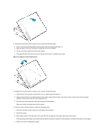
cables out of the way so that they do not catch on the computer cover. Make sure cables are not routed over the drive cage-they will prevent the cover from closing properly. 2. Facing the left side of the computer, hold the cover at a slight angle as shown in Figure 2. 3. Fit the three - Dell OptiPlex GX200 | Service Manual - Page 22
Figure 3. Inside the Chassis 1 Drive in upper bay 2 Internal drive cage 3 Chassis intrusion switch 4 Drive interface cable 5 Expansion-card cage 6 Security cable slot 7 I/O ports and connectors 8 AC power receptacle 9 Padlock ring 10 Power supply 11 System board 12 Drive interface cable Front-Panel - Dell OptiPlex GX200 | Service Manual - Page 23
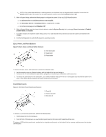
of the top cover, use your thumbs to press opening, and then press the ring tabs over the posts. Expansion-Card Cage Figure 5. Control Panel Removal 1 Slots (2) 2 Tabs (2) 3 Securing lever To remove the card cage, complete the following steps: 1. Rotate the lever toward the back of the computer - Dell OptiPlex GX200 | Service Manual - Page 24
cable To remove the control panel, perform the following steps: 1. Remove the hard-disk drive cage. 2. Disconnect the control panel cable from the PANEL connector on the system board (see Figure 14 or the internal service label for the location of the PANEL connector). 3. Remove the mounting screw - Dell OptiPlex GX200 | Service Manual - Page 25
computer cover. 2. Remove the drive bracket from the chassis. If a hard-disk drive is already installed on the drive bracket, disconnect the DC power cable and EIDE cable from the drive. 3. Remove the screw securing the hard-disk drive bracket to the front wall of the chassis. Grasp the front part - Dell OptiPlex GX200 | Service Manual - Page 26
replacing a drive in the 1inch slot, use the four screw holes in the bottom of the bracket. Hard-Disk Drive Replacement 1. Reinstall the hard-disk drive bracket in system. 2. Connect one of the device connectors on the EIDE cable to the 40-pin interface connector on the back of the hard-disk drive - Dell OptiPlex GX200 | Service Manual - Page 27
operating system for instructions. 9. Install your operating system on your hard-disk drive. Refer to the documentation that came with your operating system. System Power Supply System Power Supply Rotation To access some components on the system board, you may have to rotate the system power supply - Dell OptiPlex GX200 | Service Manual - Page 28
the system power supply. 2. Disconnect the power cables from all drives. 3. Remove the power supply cables from the system board. 4. Lift the front of the power supply until it stops. Then rotate the power supply away from the chassis. 5. Lift the power supply out of the chassis. System Power Supply - Dell OptiPlex GX200 | Service Manual - Page 29
System-Board Jumper Settings Jumper PSWD SAFE BIOS RTCRST Setting (default) (default) (default) (default) (default) Description Password features are enabled. Password features are disabled. Reserved (do not change). Reserved (do not change). Real-time clock reset. Can be used for troubleshooting - Dell OptiPlex GX200 | Service Manual - Page 30
fan connector Hard-disk drive LED connector EIDE interface connector Chassis intrusion switch connector Keyboard connector Modem audio connector Video connector Mouse connector Control panel connector Parallel port connector; sometimes referred to as LPT1 PCI expansion-card connector Main power - Dell OptiPlex GX200 | Service Manual - Page 31
automatically start up the system when they are connected. To guard against electric shock, be sure to unplug your computer from its electrical outlet before installing any expansion cards. 2. Remove the expansion-card cage. 3. If the card-slot opening for the slot you intend to use is covered by - Dell OptiPlex GX200 | Service Manual - Page 32
-level OptiPlex sound card, disconnect the internal speaker cable from the system board and reconnect it to the INT SPKR connector on the sound card. You may have to route the speaker cable through a hole in the front of the chassis to reach the sound card connector. 10. Replace the computer cover - Dell OptiPlex GX200 | Service Manual - Page 33
). 2. Press the clips outward until they snap open. 3. Press the RIMM straight into the slot running Dell recommends that only a technically knowledgeable person perform this procedure. To replace a microprocessor, perform the following steps: 1. Remove the computer cover. 2. Rotate the power supply - Dell OptiPlex GX200 | Service Manual - Page 34
by gently pushing down on the folded part of the retaining clip with a small screwdriver to the microprocessor and the computer when you turn on the system. 8. Install the microprocessor Because the system uses a ZIF socket, there is no need to use force (which system board until it snaps into place, - Dell OptiPlex GX200 | Service Manual - Page 35
the power supply back into place. 13. Replace the computer cover. 14. Reset the chassis intrusion detector. While in System Setup, confirm that the system data . Discard used batteries according to the manufacturer's instructions. To remove the system battery, perform the following steps: - Dell OptiPlex GX200 | Service Manual - Page 36
: 1. Remove the computer cover. 2. Disconnect all cables from the system board. 3. Rotate the system power supply out of the way. 4. Remove the RIMMs. 5. Remove the microprocessor. 6. Remove the AGP card brace and the AGP video card. 7. Slide all externally accessible drives and brackets partially - Dell OptiPlex GX200 | Service Manual - Page 37
7. Reinstall all components on the system board by performing steps 2 through 8 of the removal process in reverse. 8. Replace the computer cover. 9. Reset the chassis intrusion detector. While in System Setup, confirm that the system data area correctly identifies the type of microprocessor - Dell OptiPlex GX200 | Service Manual - Page 38
Parts: Dell™ OptiPlex™ GX200 Systems Service Manual Overview Recommended Tools Precautionary Measures Internal Views Computer Cover Front Bezel Eject, Power, and Reset Buttons Front-Panel Inserts Control Panel Chassis Intrusion Switch Drives System Power Supply Expansion-Card Cage Riser Boards - Dell OptiPlex GX200 | Service Manual - Page 39
side view of the mini tower chassis computer to help orient you when you work inside the computer. Figure 1. Mini Tower Chassis Orientation View 1 System board 2 Power supply 3 5.25-inch drive slots 4 Internal hard-disk drive bracket 5 Expansion-card cage 6 Bottom of computer Figure 2 shows the mini - Dell OptiPlex GX200 | Service Manual - Page 40
begins to load into memory, allow the system to complete the load operation, shut down the system, and try again. 4. Restore the system configuration settings. NOTE: If the system does not have an audio expansion card but does have an integrated audio controller, be sure that the Sound setting is On - Dell OptiPlex GX200 | Service Manual - Page 41
drive: a. Set Diskette Drive A and Diskette Drive B to Not Installed. b. Set Secondary Drive 0 or Secondary Drive 1, as appropriate, to Auto. c. Go to the second page and set Diskette to Off. 6. While in System slots at the bottom of the mini tower chassis. 2. Rotate the bezel toward the chassis - Dell OptiPlex GX200 | Service Manual - Page 42
eject button, pull gently on the plastic part of the button until it comes free. 3. To remove the power button or the reset button, use a small screwdriver and push in the two on the inside of the bay opening, and then press the ring-tabs over the posts. Control Panel Figure 8. Control Panel - Dell OptiPlex GX200 | Service Manual - Page 43
control panel cable from the control panel connector on the system board (see "System Board Labels" for the location of the PANEL connector). Remove the control panel cable. 5. Pull the control panel cable through the opening in the front wall, and carefully remove the cable from the routing tab - Dell OptiPlex GX200 | Service Manual - Page 44
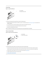
to your left and right as you face the front of the computer. Figure 10. Drive Locations 1 3.5-inch diskette drive 2 5.25-inch drive slots (3) 3 3.5-inch internal bay for hard-disk drives (2) 3.5-Inch Diskette Drive Figure 11. Diskette Drive Removal 1 Release tab To remove the 3.5-inch diskette - Dell OptiPlex GX200 | Service Manual - Page 45
drive. 5.25-Inch Drive Figure 12. 5.25-Inch Drive Removal 1 Bracket tabs (2) To remove a 5.25-inch drive from a drive bay, perform the following steps. NOTE: For easier access inside the chassis, you may want to rotate the power supply computer cover around the 5.25-inch bezel. Adjust the drive - Dell OptiPlex GX200 | Service Manual - Page 46
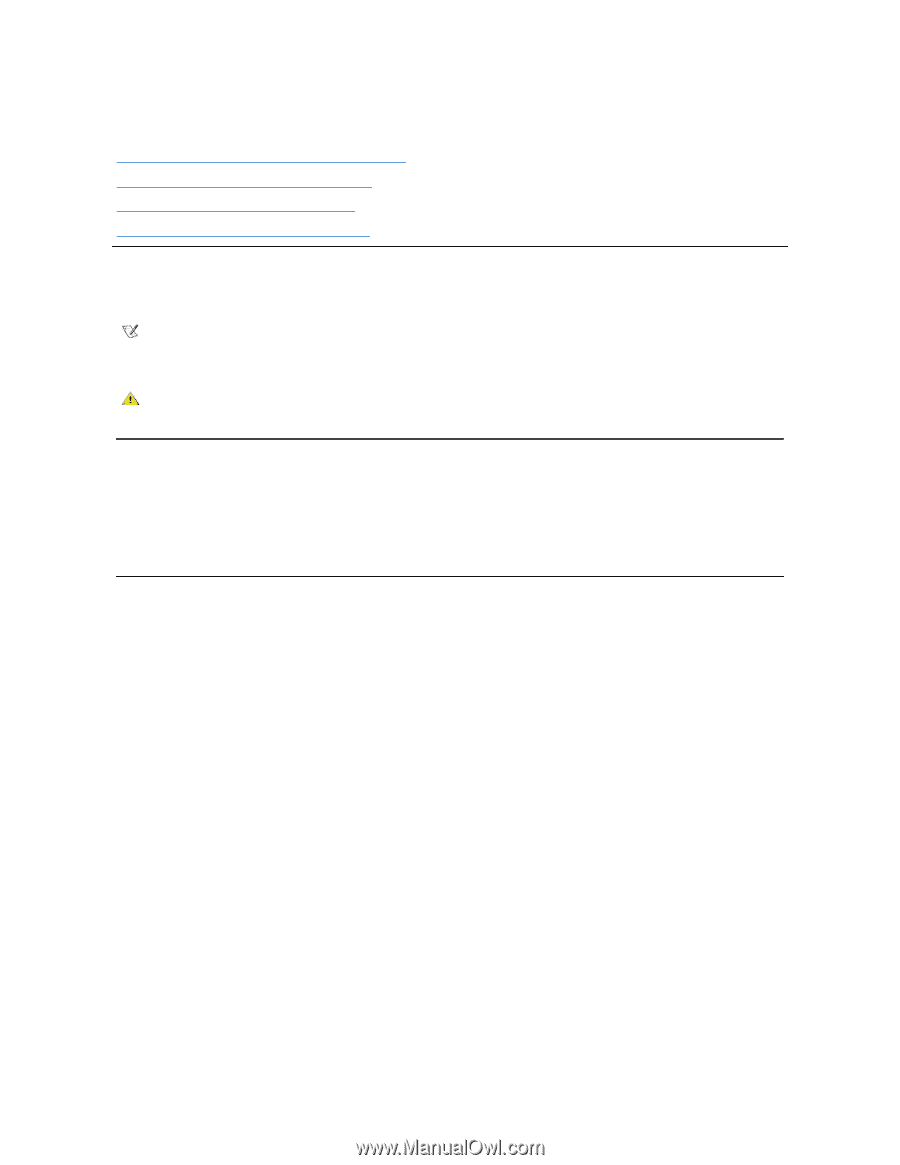
connector on the back of the drive (see Figure 15). If your system came with an EIDE CD-ROM or tape drive, use the spare connector on the existing interface cable. Otherwise, use the EIDE interface cable provided in the drive kit. Hard-Disk Drive Removal Figure 16. Hard-Disk Drive Bracket Removal - Dell OptiPlex GX200 | Service Manual - Page 47
files before you continue this procedure. 2. Remove the computer cover. 3. Remove the front bezel. 4. Open the drive bracket from the chassis: a. Disconnect the DC power cable and EIDE cable from the drive. b. Remove the screw securing the hard-disk drive bracket to the chassis. c. Grasp the bracket - Dell OptiPlex GX200 | Service Manual - Page 48
set it on a hard surface, which may damage the drive. Instead, set the drive on a surface, such as a foam pad, that will sufficiently cushion it. 1. Prepare the drive for installation. Check the documentation for the drive to verify that it is configured for your computer system. 2. If not already - Dell OptiPlex GX200 | Service Manual - Page 49
system on the hard-disk drive. For instructions, refer to the documentation that came with your operating system. System Power Supply Figure 20. Power Supply Removal 1 AC power cable 2 AC power receptacle 3 Power supply cradle 4 DC power cables 5 Securing tab To remove the system power - Dell OptiPlex GX200 | Service Manual - Page 50
the power supply down and away from the computer. Expansion-Card Cage NOTICE: Use a wrist grounding strap as explained in "Precautionary Measures." To remove the expansion-card cage, perform the following steps: 1. Examine any cables connected to expansion cards through the back-panel openings - Dell OptiPlex GX200 | Service Manual - Page 51
power connector Figure 23. Mini Tower Chassis PCI/ISA Riser Board computer. 1. Remove the expansion-card cage. 2. Remove the expansion cards installed in the slots. 3. Remove the screws securing the riser board to the expansion-card cage. System Board Components Figure 24 shows the system board - Dell OptiPlex GX200 | Service Manual - Page 52
sockets (2) 12 DC power 1 connector 13 DC power 2 connector 14 Chassis intrusion connector 15 Control panel connector 16 External speaker connector 17 EIDE1 connector 18 EIDE2 connector 19 System board speaker 20 System board jumpers 21 Diskette/tape-drive connector 22 Riser board connector 23 Real - Dell OptiPlex GX200 | Service Manual - Page 53
System-Board Jumper Settings Jumper PSWD SAFE BIOS RTCRST Setting (default) (default) (default) (default) (default) Description Password features are enabled. Password features are disabled. Reserved (do not change). Reserved (do not change). Real-time clock reset. Can be used for troubleshooting - Dell OptiPlex GX200 | Service Manual - Page 54
referred to as LPT1 PCI expansion-card connector Main power input connector 3.3-V power input connector Riser board connector Serial port connector Primary microprocessor connector USB connectors Expansion Cards Each GX200 chassis can accommodate 32-bit PCI expansion cards and 16-bit and 8-bit ISA - Dell OptiPlex GX200 | Service Manual - Page 55
with the card for information about the card's cable connections. 6. Replace the computer cover and reset the chassis intrusion detector. Memory To remove a Rambus in-line memory module (RIMM), perform the following steps: 1. Remove the computer cover. 2. Remove the system power supply to allow - Dell OptiPlex GX200 | Service Manual - Page 56
). 2. Press the clips outward until they snap open. 3. Press the RIMM straight into the slot running Dell recommends that only a technically knowledgeable person perform this procedure. To replace a microprocessor, perform the following steps: 1. Remove the computer cover. 2. Rotate the power supply - Dell OptiPlex GX200 | Service Manual - Page 57
sink assembly 4. Remove the metal retaining clip that secures the heat sink assembly to the microprocessor package by gently pushing down on the folded part of the retaining clip with a small screwdriver. The retaining clip hooks over the sides of the zero insertion force (ZIF) socket. Figure 32 - Dell OptiPlex GX200 | Service Manual - Page 58
toward the system board until it microprocessor package. Using the old heat tabs located above the system cooling fan. b. Position the power supply back into place (see Figure 20). 13. Replace the computer cover. 14. Reset the chassis intrusion detector. While in System Setup, confirm that the system - Dell OptiPlex GX200 | Service Manual - Page 59
the back of the computer. 3. Remove the expansion-card cage. 4. Unlatch and rotate the power supply until it locks (see Figure 20). 5. Remove the airflow shroud from the microprocessor. 6. Disconnect all cables from the system board. 7. Remove the screw that secures the system board to the bottom of - Dell OptiPlex GX200 | Service Manual - Page 60
lock it into position (do not twist the system board). 5. Reconnect all cables to the system board. 6. Replace the airflow shroud. 7. Replace the expansion-card cage. 8. Rotate the power supply back into place (see Figure 20). 9. Replace the computer cover. 10. Reset the chassis intrusion detector - Dell OptiPlex GX200 | Service Manual - Page 61
Parts: Dell™ OptiPlex™ GX200 Systems Service Manual Overview Recommended Tools Precautionary Measures Internal Views Computer Cover Eject and Power Buttons Control Panel Chassis Intrusion Switch Drives System Power Supply Expansion-Card Cage Riser Board System Board Components Expansion Cards - Dell OptiPlex GX200 | Service Manual - Page 62
Views Figure 1 shows a top view of the chassis to help you orient yourself when you work inside the computer. Figure 1. Orientation View 1 System board 2 Diskette drive 3 Hard-disk drive 4 CD-ROM drive 5 Power supply Figure 2 shows the chassis with the cover removed. Figure 2. Inside the Chassis - Dell OptiPlex GX200 | Service Manual - Page 63
cover. To reset the chassis intrusion detector, perform the following steps: 1. Reconnect all cables to their connectors at the back of the computer. 2. Restart the system. 3. Enter System Setup. To do this, press when F2=Setup appears in the upper-right corner of the screen. If the operating - Dell OptiPlex GX200 | Service Manual - Page 64
following steps: 1. Lay the computer cover on a flat work surface, with the inside of the top cover facing up. 2. To remove the 3.5-inch diskette-drive eject button, pull gently on the plastic part of the button until it comes free. 3. To remove the power button, use a small screwdriver and push in - Dell OptiPlex GX200 | Service Manual - Page 65
control panel connector on the system board (see "System Board Labels" for the location following steps: 1. Remove the drive shelf. 2. Remove the power supply. 3. Remove the control panel. and cable. 7. Replace the computer cover and reset the chassis intrusion detector. Drives NOTE: In all of the - Dell OptiPlex GX200 | Service Manual - Page 66
switch 2 CD-ROM drive 3 3.5-inch diskette drive 4 Hard-disk drive Preliminary Steps You must remove the drive shelf before removing the 3.5-inch diskette drive, the CD-ROM drive, the hard-disk drive, the control panel, the chassis intrusion switch, or the power supply. Figure 9. Drive Shelf Removal - Dell OptiPlex GX200 | Service Manual - Page 67
continue this procedure. 2. Remove the computer cover if not already removed. 3. Remove the drive shelf. 4. Squeeze the tabs on each side of the hard-disk drive/bracket, and pull the hard-disk drive/bracket forward about one inch (see Figure 10). 5. Disconnect the power and interface cables from the - Dell OptiPlex GX200 | Service Manual - Page 68
online System User's Guide for complete information on System Setup). After you update the System Setup settings, reboot the system. 15. Partition and logically format your computer's hard-disk drive before proceeding to the next step. See the documentation for your operating system for instructions - Dell OptiPlex GX200 | Service Manual - Page 69
necessary, press on the latch from the bottom of the drive shelf. 4. Replace the drive shelf and connect the interface and power cable connectors. CD-ROM Drive Figure 14. CD-ROM Drive Removal 1 Drive release tab To remove a CD-ROM drive, perform the following steps. NOTE: This procedure assumes that - Dell OptiPlex GX200 | Service Manual - Page 70
's Guide for more information. 5. Reset the chassis intrusion detector. System Power Supply Figure 17. Power Supply Removal 1 Securing screw hole 2 AC power receptacle 3 Power supply 4 System board DC power connectors (2) 5 Drive DC power connectors (3) To remove the system power supply, perform - Dell OptiPlex GX200 | Service Manual - Page 71
fully seated in the RISER connector on the system board. 3. Reconnect any cables you removed in step 2 of the previous procedure. 4. Replace the computer cover and reset the chassis intrusion detector. Riser Board Figure 19. PCI Riser Board 1 Auxiliary power indicator LED (AUX_LED) 2 Wakeup On LAN - Dell OptiPlex GX200 | Service Manual - Page 72
sockets (2) 12 DC power 1 connector 13 DC power 2 connector 14 Chassis intrusion connector 15 Control panel connector 16 External speaker connector 17 EIDE1 connector 18 EIDE2 connector 19 System board speaker 20 System board jumpers 21 Diskette/tape-drive connector 22 Riser board connector 23 Real - Dell OptiPlex GX200 | Service Manual - Page 73
System-Board Jumper Settings Jumper PSWD SAFE BIOS RTCRST Setting (default) (default) (default) (default) (default) Description Password features are enabled. Password features are disabled. Reserved (do not change). Reserved (do not change). Real-time clock reset. Can be used for troubleshooting - Dell OptiPlex GX200 | Service Manual - Page 74
; sometimes referred to as LPT1 PCI expansion-card connector Main power input connector 3.3-V power input connector Riser board connector Serial port connector Primary microprocessor connector USB connectors Expansion Cards The small form-factor GX200 chassis can accommodate up to two half-length - Dell OptiPlex GX200 | Service Manual - Page 75
for the card for information about the card's cable connections. 6. Replace the computer cover. 7. Reset the chassis intrusion detector. Memory To remove a Rambus in-line memory module (RIMM), perform the following steps: 1. Remove the computer cover. 2. Remove the system power supply to allow - Dell OptiPlex GX200 | Service Manual - Page 76
of the socket (see Figure 26). 2. Press the clips outward until they snap open. 3. Press the RIMM straight into the slot running down the center of the the computer cover. 5. Reset the chassis intrusion detector. Figure 26. RIMM Installation 1 Securing clips (2) 2 Notches (2) 6. Run the Dell - Dell OptiPlex GX200 | Service Manual - Page 77
computer cover. 2. Disconnect the cooling fan power cable from its system board connector. 3. Remove the metal retaining clip that secures the cooling fan/heat sink assembly to the microprocessor package by gently pushing down on the folded part the system uses a ZIF socket, there is no need to use - Dell OptiPlex GX200 | Service Manual - Page 78
on the bottom edge of the ZIF socket. 10. Reconnect the cooling fan power cable to its system board connector. 11. Replace the computer cover and restart the system. 12. Enter System Setup and confirm that the system data area correctly identifies the type of microprocessor installed. 13. Reset the - Dell OptiPlex GX200 | Service Manual - Page 79
from their connectors at the back of the computer. 2. Remove the drive shelf assembly. 3. Remove the expansion-card cage. 4. Remove the hard-disk drive/bracket. 5. Disconnect all cables from the system board. 6. Remove the screw that secures the system board to the bottom of the chassis (see Figure
-
 1
1 -
 2
2 -
 3
3 -
 4
4 -
 5
5 -
 6
6 -
 7
7 -
8
-
9
-
10
-
11
-
12
-
13
-
14
-
15
-
16
-
17
-
18
-
19
-
20
-
21
-
22
-
23
-
24
-
25
-
26
-
27
-
28
-
29
-
30
-
31
-
32
-
33
-
34
-
35
-
36
-
37
-
38
-
39
-
40
-
41
-
42
-
43
-
44
-
45
-
46
-
47
-
48
-
49
-
50
-
51
-
52
-
53
-
54
-
55
-
56
-
57
-
58
-
59
-
60
-
61
-
62
-
63
-
64
-
65
-
66
-
67
-
68
-
69
-
70
-
71
-
72
-
73
-
74
-
75
-
76
-
77
-
78
-
79
 |
 |
Dell™ OptiPlex™ GX200 Service Manual
Small Form
-
Factor Chassis
—
Removing and Replacing Parts
Low
-
Profile Chassis
—
Removing and Replacing Parts
Midsize Chassis
—
Removing and Replacing Parts
Mini Tower Chassis
—
Removing and Replacing Parts
Notes, Notices, and Cautions
Throughout this guide, blocks of text may be accompanied by an icon and printed in bold type or in italic type. These blocks are notes, notices,
and cautions, and they are used as follows:
Information in this document is subject to change without notice.
©
2000 Dell Computer Corporation. All rights reserved.
Reproduction in any manner whatsoever without the written permission of Dell Computer Corporation is strictly forbidden.
Trademarks used in this text:
Dell
and
OptiPlex
are trademarks of Dell Computer Corporation.
Other trademarks and trade names may be used in this document to refer to either the entities claiming the marks and names or their products. Dell Computer Corporation
disclaims any proprietary interest in trademarks and trade names other than its own.
Initial release: 18 April 2000
Last revised: 31 Jul 2000
NOTE: A NOTE indicates important information that helps you make better use of your system.
NOTICE: A NOTICE indicates either potential damage to hardware or loss of data and tells you how to avoid the problem.
CAUTION: A CAUTION indicates a potentially hazardous situation which, if not avoided, may result in minor or moderate
injury.