Dell OptiPlex GX200 Service Manual - Page 30
Expansion Cards, Expansion-Card Removal - video card
 |
View all Dell OptiPlex GX200 manuals
Add to My Manuals
Save this manual to your list of manuals |
Page 30 highlights
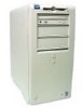
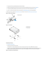
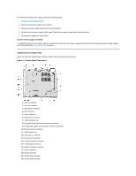
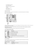
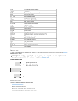
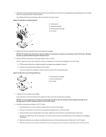
CD_IN RIMM_x DSKT ENET EXT_SPKR FAN HDLED IDEn INTRUDER KYBD MODEM MONITOR MOUSE PANEL PARALLEL PCIn* POWER_1 POWER_2 RISER SERIALn SLOT1_PRI USB CD-ROM audio interface connector RIMM socket Diskette/tape drive interface connector Integrated NIC connector External speaker connector Microprocessor fan connector Hard-disk drive LED connector EIDE interface connector Chassis intrusion switch connector Keyboard connector Modem audio connector Video connector Mouse connector Control panel connector Parallel port connector; sometimes referred to as LPT1 PCI expansion-card connector Main power input connector 3.3-V power input connector Riser board connector Serial port connector Primary microprocessor connector USB connectors Expansion Cards The system accommodates up to six expansion cards, including up to five 32-bit PCI expansion cards and one 32-bit AGP card. (See Figure 16 for examples of these cards.) NOTES: Before disconnecting a peripheral from the system or removing a component from the system board, verify that the standby power LED on the system board is off. For the location of this LED, see Figures 19 and 20. Figure 16. Expansion Cards 1 8-bit ISA expansion card 2 16-bit ISA expansion card 3 32-bit PCI expansion card Expansion-Card Removal To remove an expansion card, perform the following steps: 1. Remove the computer cover. 2. Remove the expansion-card cage. 3. If necessary, disconnect any cables connected to the card. 4. Unscrew the mounting bracket of the card you want to remove.
-
 1
1 -
2
-
3
-
4
-
5
-
6
-
7
-
8
-
9
-
10
-
11
-
12
-
13
-
14
-
15
-
16
-
17
-
18
-
19
-
20
-
21
-
22
-
23
-
24
-
 25
25 -
 26
26 -
 27
27 -
 28
28 -
 29
29 -
 30
30 -
 31
31 -
 32
32 -
 33
33 -
 34
34 -
 35
35 -
36
-
37
-
38
-
39
-
40
-
41
-
42
-
43
-
44
-
45
-
46
-
47
-
48
-
49
-
50
-
51
-
52
-
53
-
54
-
55
-
56
-
57
-
58
-
59
-
60
-
61
-
62
-
63
-
64
-
65
-
66
-
67
-
68
-
69
-
70
-
71
-
72
-
73
-
74
-
75
-
76
-
77
-
78
-
79
 |
 |