Dell OptiPlex GX200 Service Manual - Page 70
System Power Supply, Expansion-Card Cage
 |
View all Dell OptiPlex GX200 manuals
Add to My Manuals
Save this manual to your list of manuals |
Page 70 highlights
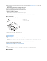
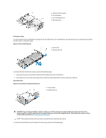
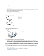
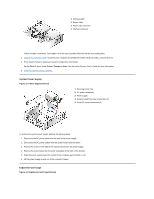
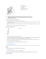
1 Interface cable 2 Power cable 3 Power input connector 4 Interface connector Check all cable connections. Fold cables out of the way to provide airflow for the fan and cooling vents. 3. Replace the computer cover; reconnect your computer and peripherals to their electrical outlets, and turn them on. 4. Enter System Setup to update your system configuration information. Set the Drive 1 option under Drives: Primary to Auto. See the online System User's Guide for more information. 5. Reset the chassis intrusion detector. System Power Supply Figure 17. Power Supply Removal 1 Securing screw hole 2 AC power receptacle 3 Power supply 4 System board DC power connectors (2) 5 Drive DC power connectors (3) To remove the system power supply, perform the following steps: 1. Disconnect the AC power cable from the back of the power supply. 2. Disconnect the DC power cables from the system board and the drives. 3. Remove the screw on the side of the chassis that secures the power supply. 4. Remove the screw below the AC power receptacle at the back of the chassis. 5. Slide the power supply toward the center of the computer approximately 1 inch. 6. Lift the power supply up and out of the computer chassis. Expansion-Card Cage Figure 18. Expansion-Card Cage Removal
-
 1
1 -
2
-
3
-
4
-
5
-
6
-
7
-
8
-
9
-
10
-
11
-
12
-
13
-
14
-
15
-
16
-
17
-
18
-
19
-
20
-
21
-
22
-
23
-
24
-
25
-
26
-
27
-
28
-
29
-
30
-
31
-
32
-
33
-
34
-
35
-
36
-
37
-
38
-
39
-
40
-
41
-
42
-
43
-
44
-
45
-
46
-
47
-
48
-
49
-
50
-
51
-
52
-
53
-
54
-
55
-
56
-
57
-
58
-
59
-
60
-
61
-
62
-
63
-
64
-
 65
65 -
 66
66 -
 67
67 -
 68
68 -
 69
69 -
 70
70 -
 71
71 -
 72
72 -
 73
73 -
 74
74 -
 75
75 -
76
-
77
-
78
-
79
 |
 |
