Dell OptiPlex GX200 Service Manual - Page 39
Mini Tower Chassis Orientation View, Inside the Mini Tower Chassis,
 |
View all Dell OptiPlex GX200 manuals
Add to My Manuals
Save this manual to your list of manuals |
Page 39 highlights
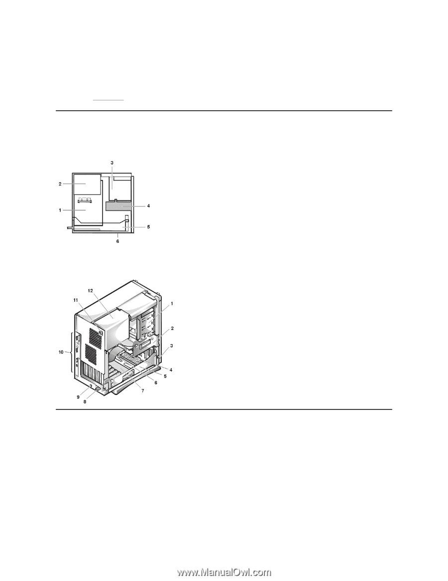
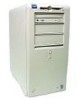
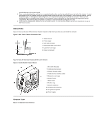
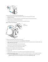
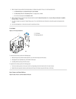
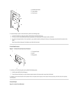
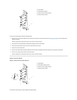
possible damage to the system board. 4. Wear a wrist grounding strap, and clip it to an unpainted metal surface, such as the padlock loop on the back of the chassis. If a wrist grounding strap is not available, touch any unpainted metal surface on the back of the computer or on the computer chassis, such as the power supply, to discharge any static charge from your body before touching anything inside the computer. While you work, periodically touch an unpainted metal surface on the computer chassis to dissipate any static electricity that might harm internal components. Also avoid touching components or contacts on a card and avoid touching pins on a chip. 5. Verify that the auxiliary power indicator on the riser board is not on. If it is on, you may need to wait 10 to 30 seconds for it to go out (see Riser Boards). Internal Views Figure 1 shows a side view of the mini tower chassis computer to help orient you when you work inside the computer. Figure 1. Mini Tower Chassis Orientation View 1 System board 2 Power supply 3 5.25-inch drive slots 4 Internal hard-disk drive bracket 5 Expansion-card cage 6 Bottom of computer Figure 2 shows the mini tower chassis with the cover removed. Figure 2. Inside the Mini Tower Chassis 1 5.25-inch drive slots 2 Hard-disk drive bracket 3 Chassis intrusion switch 4 Hard-disk drive interface cable 5 Expansion-card cage 6 System board 7 Riser board 8 Padlock ring 9 Security cable slot 10 I/O ports and connectors 11 AC power receptacle 12 Power supply Computer Cover Figure 3. Computer Cover Removal
-
 1
1 -
2
-
3
-
4
-
5
-
6
-
7
-
8
-
9
-
10
-
11
-
12
-
13
-
14
-
15
-
16
-
17
-
18
-
19
-
20
-
21
-
22
-
23
-
24
-
25
-
26
-
27
-
28
-
29
-
30
-
31
-
32
-
33
-
 34
34 -
 35
35 -
 36
36 -
 37
37 -
 38
38 -
 39
39 -
 40
40 -
 41
41 -
 42
42 -
 43
43 -
 44
44 -
45
-
46
-
47
-
48
-
49
-
50
-
51
-
52
-
53
-
54
-
55
-
56
-
57
-
58
-
59
-
60
-
61
-
62
-
63
-
64
-
65
-
66
-
67
-
68
-
69
-
70
-
71
-
72
-
73
-
74
-
75
-
76
-
77
-
78
-
79
 |
 |