Dell OptiPlex GX200 Service Manual - Page 26
Hard-Disk Drives Cables Attachment
 |
View all Dell OptiPlex GX200 manuals
Add to My Manuals
Save this manual to your list of manuals |
Page 26 highlights
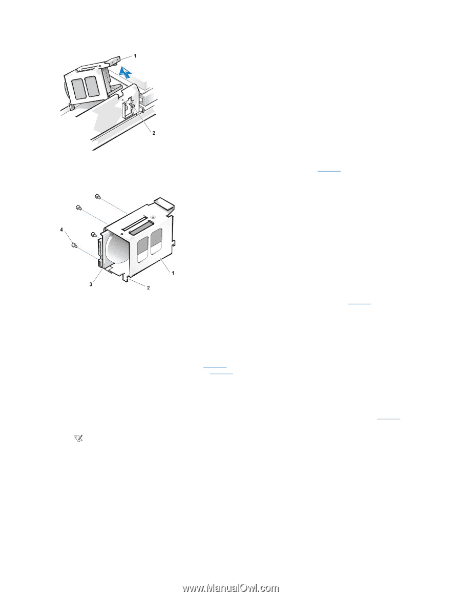
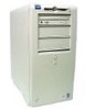
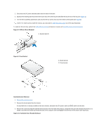
1 "Handle" on bracket 2 Screw securing drive to chassis 4. Slide the drive into the chosen bay of the bracket, orienting it so that the connectors on the back of the drive face the back of the chassis- and the power input connector is closest to the floor of the chassis-when the bracket is reinstalled (see Figure 11). Figure 11. Hard-Disk Drive Insertion 1 Drive bracket 2 Tabs (2) 3 1.6-inch drive 4 Screws (4) 5. Align the four screw holes of the drive and bracket. Insert and tighten the screws that came with your upgrade kit (see Figure 11). If you are replacing a drive in the 1.6-inch slot, use the four screw holes in the side of the bracket. If you are replacing a drive in the 1inch slot, use the four screw holes in the bottom of the bracket. Hard-Disk Drive Replacement 1. Reinstall the hard-disk drive bracket in the chassis. Hold the bracket by its handle, so that it stays at the proper tilt. Let it brush the side of the drive cage as you lower it into the chassis until the two tabs at the bottom back of the bracket (see Figure 11) fit flush against the front of the rail that extends across the chassis floor and the horizontal lip at the back fits over the rail (see Figure 12). Rotate the bracket down into position, and reinstall the screw you removed in step 3. NOTICE: You must match the colored strip on the EIDE cable with pin 1 on the IDE1 connector to avoid possible damage to your system. 2. Connect one of the device connectors on the EIDE cable to the 40-pin interface connector on the back of the hard-disk drive (see Figure 12). The cable is keyed so that the colored edge of the EIDE cable lines up with the pin-1 end of the interface connector. NOTE: Ultra Advanced Technology Attachment (ATA)/66 hard-disk drives require an 80-conductor cable to transfer data at full speed. The 80-conductor cable has a 40-pin connector just like the Ultra ATA/33 cable but has twice as many wires within the cable itself. If you use an Ultra ATA/33 cable with Ultra ATA/66 hard-disk drives, they will transfer data at Ultra ATA/33 speeds. Figure 12. Hard-Disk Drives Cables Attachment
-
 1
1 -
2
-
3
-
4
-
5
-
6
-
7
-
8
-
9
-
10
-
11
-
12
-
13
-
14
-
15
-
16
-
17
-
18
-
19
-
20
-
 21
21 -
 22
22 -
 23
23 -
 24
24 -
 25
25 -
 26
26 -
 27
27 -
 28
28 -
 29
29 -
 30
30 -
 31
31 -
32
-
33
-
34
-
35
-
36
-
37
-
38
-
39
-
40
-
41
-
42
-
43
-
44
-
45
-
46
-
47
-
48
-
49
-
50
-
51
-
52
-
53
-
54
-
55
-
56
-
57
-
58
-
59
-
60
-
61
-
62
-
63
-
64
-
65
-
66
-
67
-
68
-
69
-
70
-
71
-
72
-
73
-
74
-
75
-
76
-
77
-
78
-
79
 |
 |