Dell OptiPlex GX200 Service Manual - Page 28
System Power Supply Installation, System Board Components
 |
View all Dell OptiPlex GX200 manuals
Add to My Manuals
Save this manual to your list of manuals |
Page 28 highlights
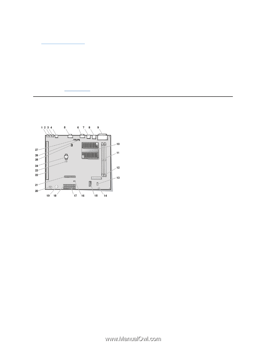
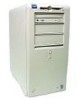
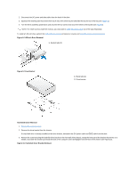
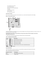
To remove the system power supply, perform the following steps: 1. Rotate the system power supply. 2. Disconnect the power cables from all drives. 3. Remove the power supply cables from the system board. 4. Lift the front of the power supply until it stops. Then rotate the power supply away from the chassis. 5. Lift the power supply out of the chassis. System Power Supply Installation To reinstall the system power supply, align the swivel points at the rear of the power supply with the holes in the chassis and power supply support arm. Then perform the removal procedure in reverse. System Board Components Figure 14 shows the system board and the location of all its sockets and connectors. Figure 14. System Board Components 1 Line-in connector 2 Line-out connector 3 Microphone connector 4 NIC connector 5 Video connector 6 Serial port 2 connector 7 USB connectors (2) 8 Keyboard (lower) and mouse (upper) connectors 9 Parallel port (upper) and serial port 1 (lower) connectors 10 Microprocessor connector 11 RIMM sockets (2) 12 DC power 1 connector 13 DC power 2 connector 14 Chassis intrusion connector 15 Control panel connector 16 External speaker connector 17 EIDE1 connector 18 EIDE2 connector 19 System board speaker 20 System board jumpers
-
 1
1 -
2
-
3
-
4
-
5
-
6
-
7
-
8
-
9
-
10
-
11
-
12
-
13
-
14
-
15
-
16
-
17
-
18
-
19
-
20
-
21
-
22
-
 23
23 -
 24
24 -
 25
25 -
 26
26 -
 27
27 -
 28
28 -
 29
29 -
 30
30 -
 31
31 -
 32
32 -
 33
33 -
34
-
35
-
36
-
37
-
38
-
39
-
40
-
41
-
42
-
43
-
44
-
45
-
46
-
47
-
48
-
49
-
50
-
51
-
52
-
53
-
54
-
55
-
56
-
57
-
58
-
59
-
60
-
61
-
62
-
63
-
64
-
65
-
66
-
67
-
68
-
69
-
70
-
71
-
72
-
73
-
74
-
75
-
76
-
77
-
78
-
79
 |
 |