Dell OptiPlex GX200 Service Manual - Page 12
System Board Jumpers - no video
 |
View all Dell OptiPlex GX200 manuals
Add to My Manuals
Save this manual to your list of manuals |
Page 12 highlights
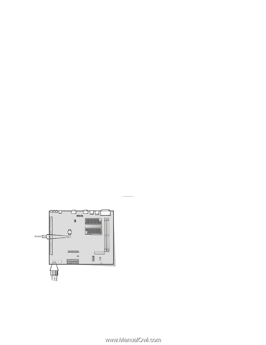
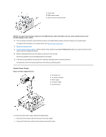
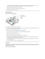
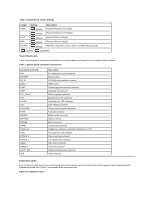
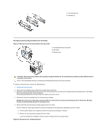
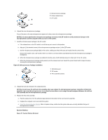
2 Line-out connector 3 Microphone connector 4 NIC connector 5 Video connector 6 Serial port 2 connector 7 USB connectors (2) 8 Keyboard (lower) and mouse (upper) connectors 9 Parallel port (upper) and serial port 1 (lower) connectors 10 Microprocessor connector 11 RIMM sockets (2) 12 DC power 1 connector 13 DC power 2 connector 14 Chassis intrusion connector 15 Control panel connector 16 External speaker connector 17 EIDE1 connector 18 EIDE2 connector 19 System board speaker 20 System board jumpers 21 Diskette/tape-drive connector 22 Riser board connector 23 Real-time clock reset (RTCRST) jumper 24 Battery 25 Modem audio connector 26 Fan connector 27 CD audio cable connector System Board Jumpers Figure 18 shows the location of the jumpers on the system board. Table 1 lists the system board jumpers and their settings. Figure 18. System Board Jumpers Jumpers are small blocks on a circuit board with two or more pins emerging from them. Plastic plugs containing a wire fit down over the pins. The wire connects the pins and creates a circuit. NOTICE: Make sure your system is turned off before you change a jumper setting. Otherwise, damage to your system or unpredictable results may occur. To change a jumper setting, pull the plug off its pin(s) and carefully fit it down onto the pin(s) indicated.
-
 1
1 -
2
-
3
-
4
-
5
-
6
-
 7
7 -
 8
8 -
 9
9 -
 10
10 -
 11
11 -
 12
12 -
 13
13 -
 14
14 -
 15
15 -
 16
16 -
 17
17 -
18
-
19
-
20
-
21
-
22
-
23
-
24
-
25
-
26
-
27
-
28
-
29
-
30
-
31
-
32
-
33
-
34
-
35
-
36
-
37
-
38
-
39
-
40
-
41
-
42
-
43
-
44
-
45
-
46
-
47
-
48
-
49
-
50
-
51
-
52
-
53
-
54
-
55
-
56
-
57
-
58
-
59
-
60
-
61
-
62
-
63
-
64
-
65
-
66
-
67
-
68
-
69
-
70
-
71
-
72
-
73
-
74
-
75
-
76
-
77
-
78
-
79
 |
 |