Epson BrightLink 1480Fi Installation Guide
Epson BrightLink 1480Fi Manual
 |
View all Epson BrightLink 1480Fi manuals
Add to My Manuals
Save this manual to your list of manuals |
Epson BrightLink 1480Fi manual content summary:
- Epson BrightLink 1480Fi | Installation Guide - Page 1
Installation Guide - Epson BrightLink 1480Fi | Installation Guide - Page 2
® EB-800F/EB-805F The BrightLink 1480Fi/1480Fi+/1485Fi/1485Fi+ is shown in most illustrations in this guide, but the steps are the same for all models unless otherwise noted. Safety Instructions For your safety, read all the instructions in this guide before using the wall mount. Incorrect - Epson BrightLink 1480Fi | Installation Guide - Page 3
in this guide If the instructions are not be performed by at least two qualified service personnel. If you need to loosen wall mount so that it can sufficiently support the weight of the projector and wall could cause the wall mount to fall. Epson accepts no responsibility for any damage or - Epson BrightLink 1480Fi | Installation Guide - Page 4
Warning Follow the instructions in this guide to install and operate the touch unit. inches (70 mm). Viewing at close range could cause injury to eyesight. Connect the touch unit to BrightLink 1480Fi/1480Fi+/1485Fi/1485Fi+/EB-725Wi/EB-735Fi models only. Do not connect it to any other projectors or - Epson BrightLink 1480Fi | Installation Guide - Page 5
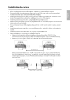
English Installation Location • Before installing the projector, verify the power supply wiring for the installation location. • If you want to hide the projector power plug under the wall plate cover, make sure the power outlet is located in the empty space to the left or right of the wall plate. - Epson BrightLink 1480Fi | Installation Guide - Page 6
. 4.0 in. (100 mm) 4.0 in. (100 mm) 0.8 in. (20 mm) • When installing the touch unit (included with the BrightLink 1485Fi/1485Fi+; available as an optional accessory for the BrightLink 1480Fi/1480Fi+/EB-725Wi/EB-735Fi) above the frame of a whiteboard, use the optional touch unit bracket. • If the - Epson BrightLink 1480Fi | Installation Guide - Page 7
English 1 Package Contents 9 2 Specifications 13 3 Connecting Devices 19 4 Positioning the Projector 21 Installation worksheet for projecting on a pre-installed wall-mounted board 22 Installation worksheet for projecting on a plain wall 24 Projection distance worksheets 25 Diagonal - Epson BrightLink 1480Fi | Installation Guide - Page 8
7 Attaching the Covers 64 Attach the wall plate cover and end cap 64 Attach the cable cover to the projector (BrightLink 1480Fi/1480Fi+/1485Fi/ 65 1485Fi+ and PowerLite EB-800F/EB-805F only) 8 Installing the Touch Unit 67 Installing the touch unit on a whiteboard 68 Install infrared - Epson BrightLink 1480Fi | Installation Guide - Page 9
1 Package Contents Wall Mount English # Part name 1 End cap 2 3-axis adjustment unit and slide plate (attached when shipped) 3 Wall mount 4 Wall plate 5 Wall plate cover 6 Hexagonal shaft 9 - Epson BrightLink 1480Fi | Installation Guide - Page 10
Use the bolts or screws supplied with the wall mount to install it as directed in this guide. Do not substitute these bolts with any other types. • You need to use commercially available wrench (for M4) *Included with the BrightLink 1480Fi/1480Fi+/1485Fi/1485Fi+/EB-725Wi/EB-735Fi projectors. 10 - Epson BrightLink 1480Fi | Installation Guide - Page 11
parts are packaged with the BrightLink 1485Fi/1485Fi+ (available as an optional accessory for the BrightLink 1480Fi/1480Fi+/EB-725Wi/EB-735Fi) and touch unit bracket (available as an optional accessory for BrightLink models listed in this guide) and are necessary when attaching the touch unit above - Epson BrightLink 1480Fi | Installation Guide - Page 12
/1485Fi+) The following parts are packaged with your projector (BrightLink 1485Fi/1485Fi+ only; available as an optional accessory for the PowerLite EB-800F/EB-805F) and are necessary when attaching the control pad. When installing - Epson BrightLink 1480Fi | Installation Guide - Page 13
English 2 Specifications Item Specification Wall mount weight (including the 3-axis adjustment unit, slide plate, wall plate, wall plate cover, and end cap) Approx. 20.3 lb (9.2 kg) Maximum load capacity 33.1 lb (15.0 kg) Vertical slide adjustment range ±1.6 in. (40 mm) Horizontal slide - Epson BrightLink 1480Fi | Installation Guide - Page 14
pieces when shipped. Use the included M4 × 12 mm bolts (×5) to attach the separate pieces together before mounting the projector. See page 43 for instructions. 5.2 in. (131 mm) 3.9 in. (99 mm) 3.9 in. (99 mm) 0.9 in. (24 mm) 1.8 in. 1.8 in. 0.9 in. (24 mm) (45 mm) (45 mm) 5.2 in. (131 mm - Epson BrightLink 1480Fi | Installation Guide - Page 15
changing the installation position of the 3-axis adjustment unit to the front or back, you can adjust the installation position of the projector. • BrightLink 1480Fi/1480Fi+/1485Fi/1485Fi+ and PowerLite EB-800F/EB-805F: Mount it at the stamp when the image is less than 80 inches diagonally, or at - Epson BrightLink 1480Fi | Installation Guide - Page 16
2.6 in. (64.8 mm) Touch unit (included with BrightLink 1485Fi/1485Fi+) External dimensions and weight The touch unit weighs approximately 21.2 ounces (600 g). 16.6 in. (422 mm) Attached labels The touch unit is a Class 1 - Epson BrightLink 1480Fi | Installation Guide - Page 17
7.8 in (198 mm) English Control pad (included with BrightLink 1485Fi/1485Fi+) External dimensions and weight The control pad weighs approximately 22.2 ounces (630 g). 7.9 in (201.8 mm) 6.9 in (174 mm) 1.4 in (36.5 mm) Cable routing - Epson BrightLink 1480Fi | Installation Guide - Page 18
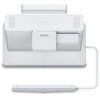
Pen stand (included with BrightLink 1485Fi/1485Fi+/EB-725Wi/EB-735Fi) External dimensions and weight The pen stand weighs approximately 3.3 ounces (93 g). 4.0 in (101.9 mm) 1.1 in (28.8 mm) 1.7 in (44.4 mm) 1.1 in (28.8 mm) 3.9 in (99.9 mm) 2.8 in (70 mm) 18 - Epson BrightLink 1480Fi | Installation Guide - Page 19
may differ slightly from the model in the illustrations. For details, refer to the online User's Guide for your projector. The connection example below shows the control pad (included with the BrightLink 1485 Fi/Fi+ only). Connection Example (For saving or importing content via USB drive) (4K30p - Epson BrightLink 1480Fi | Installation Guide - Page 20
Connecting the Control Pad The Control Pad is included with the BrightLink 1485Fi/Fi+. It provides a convenient alternative for turning on and controlling your projector. You must install the projector before installing the control pad. See page 92 for instructions. 20 - Epson BrightLink 1480Fi | Installation Guide - Page 21
sizes: This guide covers select image sizes. For other image sizes, use the Throw Distance Calculator at www.epson.com/support (U.S.), www.epson.ca/support (Canada), or www.latin.epson.com/support (Latin America). Projector BrightLink 1480Fi/1480Fi+ BrightLink 1485Fi/1485Fi+ BrightLink EB-725Wi - Epson BrightLink 1480Fi | Installation Guide - Page 22
area (f) Distance from top of image area to bottom of Touch Unit (if applicable): BrightLink 1480Fi/1480Fi+/1485Fi/ 0.79 to 2 inches (20 to 50 mm) for 16:6 1485Fi+ (BrightLink 1485Fi/1485Fi+ only) and 21:9 aspect ratios BrightLink EB-735Fi 1.61 to 2 inches (41 to 50 mm) for 16:6 aspect ratio - Epson BrightLink 1480Fi | Installation Guide - Page 23
/EB-800F/EB-805F only. **BrightLink 1480Fi/1480Fi+/1485Fi/1485Fi+ and PowerLite EB-800F/EB-805F only. If your desired aspect ratio does not match the native aspect ratio of your product, use the Throw Distance Calculator at www.epson.com/support (U.S.), www.epson.ca/support (Canada), or www.latin - Epson BrightLink 1480Fi | Installation Guide - Page 24
. **BrightLink 1480Fi/1480Fi+/1485Fi/1485Fi+ and PowerLite EB-800F/EB-805F only. If your desired aspect ratio does not match the native resolution of your product, use the Throw Distance Calculator at www.epson.com/support (U.S.), www.epson.ca/support (Canada), or www.latin.epson.com/support (Latin - Epson BrightLink 1480Fi | Installation Guide - Page 25
template sheet with the (c) mark, then align the center line on the template sheet with the center of the image area. Follow the instructions on page 43 to install the projector. Projection distance worksheets The tables on the following pages provide installation information for select image sizes - Epson BrightLink 1480Fi | Installation Guide - Page 26
mounting position b + x d c a S x In order to see the stamp and the numbers on the slider scale (b), you need to slide out the arm extension. • BrightLink 1480Fi/1480Fi+/1485Fi/1485Fi+ and PowerLite EB-800F/EB-805F: Mount it at the stamp when the image is less than 80 inches diagonally, or at - Epson BrightLink 1480Fi | Installation Guide - Page 27
Tele mode, the quality of the projected images may decrease. When projecting in the 16:6 (BrightLink 1485Fi/1485Fi+/EB-735Fi and PowerLite EB750F/EB-755F/EB-800F/EB-805F) or 21:9 (BrightLink 1480Fi/1480Fi+/1485Fi/1485Fi+ and PowerLite EB-800F/EB-805F) aspect ratio, the projected image has black bars - Epson BrightLink 1480Fi | Installation Guide - Page 28
BrightLink 1480Fi/1480Fi+/1485Fi/1485Fi+ and PowerLite EB-800F/EB-805F Measurements in Inches for , the minimum ceiling height is reduced by the corresponding measurement. **Interactive features not supported for images larger than 100". Measurements in Centimeters for 16:9 Diagonal Min. ceiling - Epson BrightLink 1480Fi | Installation Guide - Page 29
BrightLink 1480Fi/1480Fi+/1485Fi/1485Fi+ and PowerLite EB-800F/EB-805F Measurements in Inches for 16:6 (BL 1485Fi/1485Fi+ and PL EB-800F/EB-805F) Default Screen Position - Epson BrightLink 1480Fi | Installation Guide - Page 30
BrightLink 1480Fi/1480Fi+/1485Fi/1485Fi+ and PowerLite EB-800F/EB-805F Measurements in Inches lower, the minimum ceiling height is reduced by the corresponding measurement. **Interactive features not supported for images larger than 100". Measurements in Centimeters for 16:10 Diagonal Min. ceiling - Epson BrightLink 1480Fi | Installation Guide - Page 31
BrightLink 1480Fi/1480Fi+/1485Fi/1485Fi+ and PowerLite EB-800F/EB-805F Measurements in Inches for the minimum ceiling height is reduced by the corresponding measurement. **Interactive features not supported for images larger than 100". Measurements in Centimeters for 4:3 Diagonal Min. ceiling - Epson BrightLink 1480Fi | Installation Guide - Page 32
BrightLink 1480Fi/1480Fi+/1485Fi/1485Fi+ and PowerLite EB-800F/EB-805F Measurements in , the minimum ceiling height is reduced by the corresponding measurement. **Interactive features not supported for images larger than 100". Measurements in Centimeters for 21:9 Default Screen Position Screen - Epson BrightLink 1480Fi | Installation Guide - Page 33
BrightLink EB-735Fi and PowerLite EB-750F/EB-755F Measurements in Inches for 16:9 is lower, the minimum ceiling height is reduced by the corresponding measurement. **Interactive features not supported for images larger than 100". Measurements in Centimeters for 16:9 Diagonal Min. ceiling image - Epson BrightLink 1480Fi | Installation Guide - Page 34
BrightLink EB-735Fi and PowerLite EB-750F/EB-755F Measurements in Inches for 16:6 Default Screen Position Screen Position max. (top) Distance from Distance from Distance - Epson BrightLink 1480Fi | Installation Guide - Page 35
BrightLink EB-735Fi and PowerLite EB-750F/EB-755F Measurements in Inches for 16:10 Diagonal Min. ceiling image size (S) height* Image width (w) Image height (h) Distance - Epson BrightLink 1480Fi | Installation Guide - Page 36
BrightLink EB-735Fi and PowerLite EB-750F/EB-755F Measurements in Inches for 4:3 Diagonal Min. ceiling image size (S) height* Image width (w) Image height (h) Distance from top - Epson BrightLink 1480Fi | Installation Guide - Page 37
BrightLink EB-725Wi and PowerLite EB-725W Measurements in Inches for 16:10 Diagonal is lower, the minimum ceiling height is reduced by the corresponding measurement. **Interactive features not supported for images larger than 100". Measurements in Centimeters for 16:10 Diagonal Min. ceiling image - Epson BrightLink 1480Fi | Installation Guide - Page 38
BrightLink EB-725Wi and PowerLite EB-725W Measurements in Inches for 16:9 Diagonal lower, the minimum ceiling height is reduced by the corresponding measurement. **Interactive features not supported for images larger than 100". Measurements in Centimeters for 16:9 Diagonal Min. ceiling image - Epson BrightLink 1480Fi | Installation Guide - Page 39
BrightLink EB-725Wi and PowerLite EB-725W Measurements in Inches for 4:3 Diagonal Min. ceiling image size (S) height* Image width (w) Image height (h) Distance from top of image - Epson BrightLink 1480Fi | Installation Guide - Page 40
PowerLite EB-720 Measurements in Inches for 4:3 Diagonal Min. ceiling image size (S) height* Image width (w) Image height (h) Distance from top of image to Min. projection Sliderscale bottom wall plate distance (a) mark (b) holes (c) Distance from top of image to temporary wall plate hole - Epson BrightLink 1480Fi | Installation Guide - Page 41
PowerLite EB-720 Measurements in Inches for 16:9 Diagonal Min. ceiling image size (S) height* Image width (w) Image height (h) Distance from top of image to Min. projection Sliderscale bottom wall plate distance (a) mark (b) holes (c) Distance from top of image to temporary wall plate hole - Epson BrightLink 1480Fi | Installation Guide - Page 42
PowerLite EB-720 Measurements in Inches for 16:10 Diagonal Min. ceiling image size (S) height* Image width (w) Image height (h) Distance from top of image to Min. projection Sliderscale bottom wall plate distance (a) mark (b) holes (c) Distance from top of image to temporary wall plate - Epson BrightLink 1480Fi | Installation Guide - Page 43
over the wall mount. ❏ Install the wall mount so that it can sufficiently support the weight of the projector and wall mount, and resist any horizontal vibration. Use M10 or 3/8 inch could cause the wall mount to fall. ❏ Epson accepts no responsibility for any damage or injury caused by lack of wall - Epson BrightLink 1480Fi | Installation Guide - Page 44
2. BrightLink 1480Fi/1480Fi+/1485Fi/1485Fi+ and PowerLite EB-800F/EB-805F only: Loosen the two screws with a cross-head screwdriver and remove the cable cover from the projector. 3. - Epson BrightLink 1480Fi | Installation Guide - Page 45
can support the projector and wall mount. • From the projection distance table, confirm the screen size (S), the distance between the projection image and wall plate bottom holes (c), and the distance between the projection image and temporary wall plate hole (d). • BrightLink 1480Fi/1480Fi+/1485Fi - Epson BrightLink 1480Fi | Installation Guide - Page 46
2. Drive an M10 screw (not included) into the temporary wall plate hole. Leave at least 0.2 inch (6 mm) between the screw head and the wall. 3. Determine the position of the wall plate's mounting holes. Use at least four mounting holes for proper balance. 4. Drill holes of the following diameters - Epson BrightLink 1480Fi | Installation Guide - Page 47
English 7. Position the wall plate on the temporary wall plate screw. 8. Insert commercially available M10 × 60 mm or 3/8 inch anchors into the holes and secure them in place. 9. Remove the temporary wall plate screw. 47 - Epson BrightLink 1480Fi | Installation Guide - Page 48
C Determine the projection distance and pull out the mount arm slider 1. Using the tables on pages 30 to 32, check the number for the slider measure (b). 2. Loosen the M4 × 12 mm hexagon socket head cap bolts (×2), and then pull out the slider on the wall mount. Align the slider with the measure - Epson BrightLink 1480Fi | Installation Guide - Page 49
English D Route the cables through the wall mount arm For BrightLink projectors with a Touch Unit: Make sure to route the Touch Unit connection cable through the wall mount arm. Route the Touch Unit connection cable so - Epson BrightLink 1480Fi | Installation Guide - Page 50
3. Insert the hexagonal shaft into the slot at the top of the wall plate ( ). 4. Insert the hexagonal shaft into the slot at the bottom of the wall plate ( ). Caution ❏ Make sure the Touch Unit connection cable is not wired into the wall with the other cables. ❏ Take care not to trap the cables - Epson BrightLink 1480Fi | Installation Guide - Page 51
English F Adjust the vertical slide position of the arm 1. Adjust the vertical slide with the M8 hexagon bolt at the bottom of the wall mount ( ), or the hexagonal shaft at the top of the wall mount ( ). Start by aligning the notch on the arm with the alignment mark on the wall plate as shown below - Epson BrightLink 1480Fi | Installation Guide - Page 52
3-axis adjustment unit with the projector to the wall mount arm. Decide which position you want to use for installing the 3-axis adjustment unit: • BrightLink 1480Fi/1480Fi+/1485Fi/1485Fi+ and PowerLite EB-800F/EB-805F: Mount it at the stamp when the image is less than 80 inches diagonally, or at - Epson BrightLink 1480Fi | Installation Guide - Page 53
Pad cables (if applicable), and power cord to the projector. See your projector's online User Guide for detailed connection information. Use M4 screws (not included) to secure any additional devices or the image. An optional cable management system is available from Epson (part number ELPCK01). 53 - Epson BrightLink 1480Fi | Installation Guide - Page 54
I Attach a Mini PC or Stick PC if necessary You can secure a Mini PC or Stick PC to the left or the right side of the wall plate. Attach the Mini PC so that the air exhaust vents of the PC are not blocked. Install the PC so that the air exhaust vents are at the top and the air intake vents are at - Epson BrightLink 1480Fi | Installation Guide - Page 55
English 3. Rest the PC on the lip of the Mini PC plate and secure it with the band. 55 - Epson BrightLink 1480Fi | Installation Guide - Page 56
this section, but the instructions are the same except where noted. A Turn on the projector Press the power button on the remote control or the projector. B Adjust the focus 1. Open the cover ( ). 2. Use the focus lever to adjust the focus ( ). BrightLink 1480Fi/1480Fi+/1485Fi/1485Fi+ and PowerLite - Epson BrightLink 1480Fi | Installation Guide - Page 57
English C Select the screen type 1. Press the [Menu] button on the remote control or control panel. BrightLink 1480Fi/1480Fi+/1485Fi/1485Fi+ and PowerLite EB-800F/EB-805F: Remote Control Control Panel BrightLink EB-725Wi/EB-735Fi and PowerLite EB-720/EB-725W/EB-750F/EB-755F: Remote Control - Epson BrightLink 1480Fi | Installation Guide - Page 58
the 16:6 (BrightLink 1485Fi/1485Fi+/EB-735Fi and PowerLite EB-750F/EB-755F/EB-800F/ EB-805F only) or 21:9 (BrightLink 1480Fi/14840Fi+/1485Fi/1485Fi+ or control panel. BrightLink 1480Fi/1480Fi+/1485Fi/1485Fi+ and PowerLite EB-800F/EB-805F: Remote Control Control Panel BrightLink EB-725Wi/EB-735Fi - Epson BrightLink 1480Fi | Installation Guide - Page 59
English 4. The installation guide and test pattern are displayed. Use these to monitor the image as you make the E J adjustments in steps to . E Use adjustment dial 1 on the left - Epson BrightLink 1480Fi | Installation Guide - Page 60
F Use adjustment dial 2 on the top to adjust the horizontal rotation 1. Loosen the screw to unlock the adjustment dials ( ). 2. Turn the adjustment dials to adjust the horizontal rotation ( ). E J 3. After you finish making all of the adjustments in steps to , tighten the screw you loosened in . G - Epson BrightLink 1480Fi | Installation Guide - Page 61
English H Adjust the horizontal slide 1. Loosen the M4 × 12 mm hexagon socket head cap bolt ( ). 2. Adjust the slider for the slide plate ( ). E J 3. After you finish making all of the adjustments in steps to , tighten the M4 × 12 mm hexagon socket head cap bolt you loosened in . I Adjust the - Epson BrightLink 1480Fi | Installation Guide - Page 62
J Adjust the vertical slide 1. Loosen the M6 × 20 mm hexagon shoulder bolt ( ). 2. Adjust the vertical slide with the M8 hexagon bolt at the bottom of the wall mount, or the hexagonal shaft at the top of the wall mount ( ). Tightening the M8 hexagon bolt lowers the wall mount, and loosening the bolt - Epson BrightLink 1480Fi | Installation Guide - Page 63
English K Re-adjust the focus 1. Open the front cover ( ). 2. Use the focus lever to adjust the focus ( ). BrightLink 1480Fi/1480Fi+/1485Fi/1485Fi+ and PowerLite EB-800F/EB-805F: BrightLink EB-725Wi/EB-735Fi and PowerLite EB-720/EB-725W/EB-750F/EB-755F: 3. After you finish making the adjustment, - Epson BrightLink 1480Fi | Installation Guide - Page 64
7 Attaching the Covers A Attach the wall plate cover and end cap If you need to use a security cable, make sure you attach it before installing the wall plate cover. See page 105 for instructions. 1. Attach the left wall plate cover. 2. Attach the right wall plater cover. 64 - Epson BrightLink 1480Fi | Installation Guide - Page 65
If you want to cover the groove in the mount arm, attach the masking sticker as shown. B Attach the cable cover to the projector (BrightLink 1480Fi/1480Fi+/ 1485Fi/1485Fi+ and PowerLite EB-800F/EB-805F only) Attach the cable cover ( ) and use a cross-head screwdriver to tighten the screws (x2) and - Epson BrightLink 1480Fi | Installation Guide - Page 66
Caution Only a specialist should remove or reinstall the projector, including for maintenance and repairs. Refer to your online User's Guide for your projector for instructions on maintenance and repairs. Warning ❏ Never loosen the bolts and nuts after installation. If you find any loose screws, - Epson BrightLink 1480Fi | Installation Guide - Page 67
pen(s) before you install the touch unit (see the online User's Guide for more information). The touch unit is included with the BrightLink 1485Fi/1485Fi+. You can purchase it as an optional accessory for the BrightLink 1480Fi/1480Fi+/EB-725Wi/EB-735Fi. The steps for installing the touch unit vary - Epson BrightLink 1480Fi | Installation Guide - Page 68
a whiteboard Follow the steps below to install the touch unit on a whiteboard. Some menus may differ slightly from the illustrations, but the installation instructions are the same. ❏ There are magnets built in to the back of the touch unit. Typically, the touch unit should be installed by attaching - Epson BrightLink 1480Fi | Installation Guide - Page 69
. C Display the installation pattern 1. Press the [Menu] button on the remote control or control panel. BrightLink 1480Fi/1480Fi+/1485Fi/1485Fi+: Remote Control Control Panel BrightLink EB-725Wi/EB-735Fi: Remote Control Control Panel 2. Select Installation. 3. Select Touch Unit. 4. Select - Epson BrightLink 1480Fi | Installation Guide - Page 70
The Installation pattern is displayed on the projected image. D Determine the installation position for the touch unit 1. Mark the following installation positions: • ( ): The center line of the installation pattern. • ( ): 0.79 to 1.97 inches (20 to 50 mm) from the top edge of the projected image - Epson BrightLink 1480Fi | Installation Guide - Page 71
English 2. For non-magnetic boards or screens, attach the template sheet to the board. Line up the pattern on the bottom of the sheet with the top of the projected pattern. Drill two holes where indicated and remove the template sheet. 71 - Epson BrightLink 1480Fi | Installation Guide - Page 72
E Install the touch unit • For magnetic boards, place the back of the touch unit on the screen surface to secure it. Caution When installing the touch unit on a magnetic surface, be careful not to trap your fingers or any other part of your body between the magnets and the installation surface. • - Epson BrightLink 1480Fi | Installation Guide - Page 73
English Secure the touch unit with two (2) M4 screws (not included). 0.8 in. (20 mm) Re-attach the rubber caps. 73 - Epson BrightLink 1480Fi | Installation Guide - Page 74
. Operations are not possible with a commercially available cable. 2. Press the [Menu] button on the remote control or control panel. BrightLink 1480Fi/1480Fi+/1485Fi/1485Fi+: Remote Control Control Panel BrightLink EB-725Wi/EB-735Fi: Remote Control Control Panel 3. Select Installation. 74 - Epson BrightLink 1480Fi | Installation Guide - Page 75
English 4. Select Touch Unit. 5. Set Power to On. The touch unit power turns on and the power light turns blue. Warning Do not look into the projector's projection window or the touch unit's laser diffusion ports (located on the bottom of the touch unit); this could cause injury to eyesight. When - Epson BrightLink 1480Fi | Installation Guide - Page 76
. Refer to the online User's Guide for your projector for detailed instructions on calibrating the pen(s). 1. Press the [Menu] button on the remote control or control panel. BrightLink 1480Fi/1480Fi+/1485Fi/1485Fi+: Remote Control Control Panel BrightLink EB-725Wi/EB-735Fi: Remote Control - Epson BrightLink 1480Fi | Installation Guide - Page 77
. If you're using multiple projectors and the HDMI Out Setting option in the MultiProjection menu is set to Process Out, follow the on-screen instructions to turn off the Power setting for the touch unit on the next projector you set up. 5. Select Installing the Touch Unit without the bracket - Epson BrightLink 1480Fi | Installation Guide - Page 78
on the remote control or control panel to begin the auto adjustment. 8. When adjustments are complete, remove the markers. If auto adjustment fails, follow the instructions on the screen to manually adjust the angle of the laser and run auto adjustment again. 78 - Epson BrightLink 1480Fi | Installation Guide - Page 79
indicators do not appear where you touched the screen, you need to manually adjust the touch unit alignment. Select Up using the control panel or remote Touch Unit, then Touch Calibration. Follow the instructions on the screen. See the online User's Guide for more details on the touch calibration. H - Epson BrightLink 1480Fi | Installation Guide - Page 80
unit bracket to install the touch unit above the frame of a whiteboard. Some menus may differ slightly from the illustrations, but the installation instructions are the same. Install the touch unit bracket on a flat, smooth, unwarped surface. If there is unevenness on the screen surface of more - Epson BrightLink 1480Fi | Installation Guide - Page 81
. C Display the installation pattern 1. Press the [Menu] button on the remote control or control panel. BrightLink 1480Fi/1480Fi+/1485Fi/1485Fi+: Remote Control Control Panel BrightLink EB-725Wi/EB-735Fi: Remote Control Control Panel 2. Select Installation. 3. Select Touch Unit. 4. Select - Epson BrightLink 1480Fi | Installation Guide - Page 82
The Installation pattern is displayed on the projected image. D Determine the installation position for the bracket Align the bottom of the bracket template sheet with the top of the projection surface and attach the sheet to the wall. The touch unit must be installed above the image area. 82 - Epson BrightLink 1480Fi | Installation Guide - Page 83
English E Drill holes for the bracket If possible, drill holes at the four points labeled Main on the template sheet. If you're unable to use the points labeled Main, you can secure the bracket at the points labeled Sub. Make sure you secure the bracket at four points (two on the left and two on - Epson BrightLink 1480Fi | Installation Guide - Page 84
4. Slide the front of the bracket until the lower edge touches the projection surface. ❏ If the distance from the wall to the surface of the whiteboard is greater than 2 inches (51 mm), you must install the touch unit on the whiteboard. ❏ If the frame of the whiteboard extends more than 0.1 inch (3 - Epson BrightLink 1480Fi | Installation Guide - Page 85
English 7. Secure the touch unit to the bracket with the M4 × 25 mm bolts (×2) supplied. Caution When attaching the touch unit to the bracket, be careful not to trap your fingers or any other part of your body between the magnets and the bracket. 8. Re-attach the rubber caps. G Turn on the touch - Epson BrightLink 1480Fi | Installation Guide - Page 86
2. Press the [Menu] button on the remote control or control panel. BrightLink 1480Fi/1480Fi+/1485Fi/1485Fi+: Remote Control Control Panel BrightLink EB-725Wi/EB-735Fi: Remote Control Control Panel 3. Select Installation. 4. Select Touch Unit. 86 - Epson BrightLink 1480Fi | Installation Guide - Page 87
. Refer to the online User's Guide for your projector for detailed instructions on calibrating the pen(s). 1. Press the [Menu] button on the remote control or control panel. BrightLink 1480Fi/1480Fi+/1485Fi/1485Fi+: Remote Control Control Panel BrightLink EB-725Wi/EB-735Fi: Remote Control - Epson BrightLink 1480Fi | Installation Guide - Page 88
. If you're using multiple projectors and the HDMI Out Setting option in the MultiProjection menu is set to Process Out, follow the on-screen instructions to turn off the Power setting for the touch unit on the next projector you set up. 5. Select Installing the Touch Unit with the bracket - Epson BrightLink 1480Fi | Installation Guide - Page 89
English 6. Loosen the adjustment screw at the top of the bracket until it stops turning. Make sure you stop loosening the screw as soon as it stops turning. Continuing to turn the screw may remove it from the bracket. 89 - Epson BrightLink 1480Fi | Installation Guide - Page 90
on the remote control or control panel to begin the auto adjustment. 9. When adjustments are complete, remove the markers. If auto adjustment fails, follow the instructions on the screen to manually adjust the bracket position and run auto adjustment again. 90 - Epson BrightLink 1480Fi | Installation Guide - Page 91
the gray indicators do not appear where you touched the screen, you need to manually adjust the touch unit alignment. Select Up using the control panel or remote control Calibration. Follow the instructions on the screen. See the online User's Guide for more details on the touch calibration. 91 - Epson BrightLink 1480Fi | Installation Guide - Page 92
stand. Caution The control pad should only be connected to the BrightLink 1485Fi/1485Fi+ and PowerLite EB-800F/EB-805F. Do not connect the control pad to any other projectors. Previous Epson control pad models do not support HDBaseT. Check the installation location Make sure there is enough space - Epson BrightLink 1480Fi | Installation Guide - Page 93
English B Connect the power cable Connect the power cable and route it down the groove on the back of the control pad. C Attach the control pad Attach the control pad with commercially available M4 × 20 mm screws (×4). Warning ❏ Make sure the screws are not angled. ❏ Make sure the control pad is - Epson BrightLink 1480Fi | Installation Guide - Page 94
D Secure the AC adapter Secure the AC adapter holder to the wall using M4 screws (×4) Slide the AC adapter into the holder and connect the power cable. E Connect the projector cables to the control pad See the connection example on page 19 for details. 94 - Epson BrightLink 1480Fi | Installation Guide - Page 95
English F Attach the front cover Installing the pen stand The pen stand is included with the BrightLink 1485Fi/1485Fi+/EB-725Wi/EB-735Fi. You can secure the pen stand with commercially-available M4 screws (not included) or the attached magnets. A Secure the - Epson BrightLink 1480Fi | Installation Guide - Page 96
B Attach the pen stand cover. 96 - Epson BrightLink 1480Fi | Installation Guide - Page 97
Guide or visit the following site and search for your product: U.S.: www.epson.com/support/brightlinkdownloads Canada: www.epson.ca/support/brightlinkdownloads Latin America: www.latin.epson.com/support This feature is only available on the BrightLink 1480Fi/1480Fi+/1485Fi/1485Fi+/ EB-725Wi/EB-735Fi. - Epson BrightLink 1480Fi | Installation Guide - Page 98
2. Press the [Menu] button on the remote control or control panel. BrightLink 1480Fi/1480Fi+/1485Fi/1485Fi+: Remote Control Control Panel BrightLink EB-725Wi/EB-735Fi: Remote Control Control Panel 3. Select Installation. 4. Select Auto Screen Adjustment. 5. Loosen all of the adjustment dials - Epson BrightLink 1480Fi | Installation Guide - Page 99
projector or wall mount may fall and cause personal injury or property damage. 8. Open the front cover ( ). 9. Use the focus lever to adjust the focus ( ). BrightLink 1480Fi/1480Fi+/1485Fi/1485Fi+: BrightLink EB-725Wi/EB-735Fi: 10. After you finish making the adjustment, close the front cover. 99 - Epson BrightLink 1480Fi | Installation Guide - Page 100
any direction on the screen surface. 1. Press the [Menu] button on the remote control or control panel. BrightLink 1480Fi/1480Fi+/1485Fi/1485Fi+ and PowerLite EB-800F/EB-805F: Remote Control Control Panel BrightLink EB-725Wi/EB-735Fi and PowerLite EB-720/EB-725W/EB-750F/EB-755F: Remote Control - Epson BrightLink 1480Fi | Installation Guide - Page 101
with the Quick Corner setting. 1. Press the [Menu] button on the remote control or control panel. BrightLink 1480Fi/1480Fi+/1485Fi/1485Fi+ and PowerLite EB-800F/EB-805F: Remote Control Control Panel BrightLink EB-725Wi/EB-735Fi and PowerLite EB-720/EB-725W/EB-750F/EB-755F: Remote Control - Epson BrightLink 1480Fi | Installation Guide - Page 102
3. Select Geometry Correction. 4. Select Quick Corner. 5. Select the corner that you want to correct. 6. Use the arrow buttons on the remote control or control panel to change the shape of the selected corner. 7. Repeat steps 5 and 6 to adjust any additional corners. 102 - Epson BrightLink 1480Fi | Installation Guide - Page 103
with the Point Correction setting. 1. Press the [Menu] button on the remote control or control panel. BrightLink 1480Fi/1480Fi+/1485Fi/1485Fi+ and PowerLite EB-800F/EB-805F: Remote Control Control Panel BrightLink EB-725Wi/EB-735Fi and PowerLite EB-720/EB-725W/EB-750F/EB-755F: Remote Control - Epson BrightLink 1480Fi | Installation Guide - Page 104
5. Select the point on the grid that you want to correct. 6. Use the arrow buttons on the remote control or control panel to change the shape of the selected point. 7. Repeat steps 5 and 6 to adjust any additional areas. 104 - Epson BrightLink 1480Fi | Installation Guide - Page 105
For details on how to lock the wire lock, refer to the User's Guide supplied with the wire lock. If applicable, make sure you leave the remote with the projector. If your projector came with a product-specific installation guide or an installation leave-behind list, use that list instead of this one
-
 1
1 -
 2
2 -
 3
3 -
 4
4 -
 5
5 -
 6
6 -
 7
7 -
8
-
9
-
10
-
11
-
12
-
13
-
14
-
15
-
16
-
17
-
18
-
19
-
20
-
21
-
22
-
23
-
24
-
25
-
26
-
27
-
28
-
29
-
30
-
31
-
32
-
33
-
34
-
35
-
36
-
37
-
38
-
39
-
40
-
41
-
42
-
43
-
44
-
45
-
46
-
47
-
48
-
49
-
50
-
51
-
52
-
53
-
54
-
55
-
56
-
57
-
58
-
59
-
60
-
61
-
62
-
63
-
64
-
65
-
66
-
67
-
68
-
69
-
70
-
71
-
72
-
73
-
74
-
75
-
76
-
77
-
78
-
79
-
80
-
81
-
82
-
83
-
84
-
85
-
86
-
87
-
88
-
89
-
90
-
91
-
92
-
93
-
94
-
95
-
96
-
97
-
98
-
99
-
100
-
101
-
102
-
103
-
104
-
105
 |
 |
Installation Guide