Epson ColorWorks CW-C6500A Technical Reference Guide - External I/O CW-C6000/C
Epson ColorWorks CW-C6500A Manual
 |
View all Epson ColorWorks CW-C6500A manuals
Add to My Manuals
Save this manual to your list of manuals |
Epson ColorWorks CW-C6500A manual content summary:
- Epson ColorWorks CW-C6500A | Technical Reference Guide - External I/O CW-C6000/C - Page 1
Series External I/O Technical Reference Guide Series Overview External I/O Specification Commands Printer Statuses and Signals Timing Settings on the Printer Appendix M00123700 Rev.A - Epson ColorWorks CW-C6500A | Technical Reference Guide - External I/O CW-C6000/C - Page 2
product, or (excluding the U.S.) failure to strictly comply with Seiko Epson Corporation's operating and maintenance instructions. • Seiko Epson Corporation shall not be liable against any damages or problems arising from the use of any options or any consumable products other than those designated - Epson ColorWorks CW-C6500A | Technical Reference Guide - External I/O CW-C6000/C - Page 3
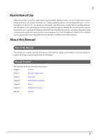
to direct medical care etc., please make your own judgment on this product's suitability after a full evaluation. About this Manual Aim of the Manual This manual was created to provide information on development, design, and installation of systems and development and design of printer applications - Epson ColorWorks CW-C6500A | Technical Reference Guide - External I/O CW-C6000/C - Page 4
odor, or unusual noise. Continued use may lead to fire or electric shock. Immediately unplug the equipment. • Only disassemble this product as described in this manual. Do not make modifications to the unit. Tampering with this product may result in injury, fire, or electric shock. • Never insert or - Epson ColorWorks CW-C6500A | Technical Reference Guide - External I/O CW-C6000/C - Page 5
Contents ■ Restriction of Use...3 ■ About this Manual ...3 Aim of the Manual ...3 Manual Content ...3 Key to Symbols...4 Safety Precautions on Handling ...4 ■ Contents ...5 Overview ...7 ■ Functionality...7 ■ External device...8 External I/O Specification 9 ■ Connector...9 ■ Signal Definitions ...9 - Epson ColorWorks CW-C6500A | Technical Reference Guide - External I/O CW-C6000/C - Page 6
■ Acquisition Commands for Setting Values 38 Acquisition commands for mode setting values for end print signal (output 38 Acquisition commands for mode setting values for data ready signal (output 38 Acquisition commands for mode setting values for clogged nozzle detected signal (output - Epson ColorWorks CW-C6500A | Technical Reference Guide - External I/O CW-C6000/C - Page 7
Chapter 1 Overview Overview This guide describes the external I/O specifications for the CW-C6000 Series/CW-C6500 Series. Please develop your device to match these specifications. Functionality Using the external I/O signal - Epson ColorWorks CW-C6500A | Technical Reference Guide - External I/O CW-C6000/C - Page 8
External device The following external devices can be connected. • Automatic application machine • Roll rewinder • Devices that must sync with the printer other than the above Q NOTE The number of possible connections is one. 8 - Epson ColorWorks CW-C6500A | Technical Reference Guide - External I/O CW-C6000/C - Page 9
Chapter 2 External I/O Specification External I/O Specification This section describes the external I/O for the printer. Connector The external I/O connectors are as follows. D-sub25 connector (female connector) Screws: Metric screws 13 1 Q NOTE 25 14 2 Be sure to use the screws to affix - Epson ColorWorks CW-C6500A | Technical Reference Guide - External I/O CW-C6000/C - Page 10
Minimum interval between input pulse signals As shown below, the interval between input pulse signals that can be received should be 50 ms or more. If pulse signals are received at an interval of less than 50 ms, the second pulse signal will not be detected. Not detected Min. 50 msec Level signal A - Epson ColorWorks CW-C6500A | Technical Reference Guide - External I/O CW-C6000/C - Page 11
a jumper on CN200 to provide an external I/ O power supply, while also keeping Signal Ground and Frame Ground separate. Input Pulse/Level Sends an instruction to start printing. • In pulse mode, printing starts if a change from High to Low is detected. Detection occurs only when the state of the - Epson ColorWorks CW-C6500A | Technical Reference Guide - External I/O CW-C6000/C - Page 12
printed is sent from an external device. • The label is reprinted if a change from High to Low is detected. • Signal logic: Low active Sends an instruction to check the head for a clogged nozzle. • The head is checked for a clogged nozzle if a change from High to Low is detected. • Signal logic: Low - Epson ColorWorks CW-C6500A | Technical Reference Guide - External I/O CW-C6000/C - Page 13
Chapter 2 External I/O Specification Pin Signal 18 End print *2 *4 19 Printer ready *2 20 Reserved 21 Head maintenance *2 22 Ink cartridge exchange*2 23 Data ready *2 InputOutput *1 Pulse/Level Description Output Pulse/Level The meaning of this signal varies depending on the values that - Epson ColorWorks CW-C6500A | Technical Reference Guide - External I/O CW-C6000/C - Page 14
Pin Signal 24 Clogged nozzle detected *2 *5 InputOutput *1 Output 25 Paper out *2 Output Pulse/Level Description Level Level Indicates whether the printer has detected a clogged nozzle in the head. • L: Clogged nozzle detected • H: Clogged nozzle not detected * The results of the previous - Epson ColorWorks CW-C6500A | Technical Reference Guide - External I/O CW-C6000/C - Page 15
Chapter 2 External I/O Specification Specification for I/O Signals This section describes the I/O signal specifications. Input/Output Item Value Input signal to the printer Type of output port on the Open drain or open collector output external device Low level VIL_max. 0.8 V Sink current - Epson ColorWorks CW-C6500A | Technical Reference Guide - External I/O CW-C6000/C - Page 16
Example output signal circuit +5 V Printer side External device side Rpu Printer output External device input SG FG SG 16 - Epson ColorWorks CW-C6500A | Technical Reference Guide - External I/O CW-C6000/C - Page 17
Chapter 3 Commands Commands This section describes the commands of the external I/O. You can acquire each signal's mode settings and printer setting values. List of Commands The signal specifications for the external I/O are as follows. No. Command name category Command function Command and - Epson ColorWorks CW-C6500A | Technical Reference Guide - External I/O CW-C6000/C - Page 18
No. Command name category Command function Command and parameters 7 External I/O out- Error signal mode setting put signal settings ^S(CNA,E,c c= D/E/0/1/2 0/D: Off 1: Normal: High, When an event occurs: Low 2/E: Normal: Low, When an event occurs: High 8 Ink low signal mode setting - Epson ColorWorks CW-C6500A | Technical Reference Guide - External I/O CW-C6000/C - Page 19
Chapter 3 Commands No. Command name category Command function Command and parameters 11 External I/O input Pause signal mode setting signal settings ^S(CNI,P,c c= 0/1 0: Ignore pause signal. 1: Switch the pause state if Low is asserted for the pause signal for 20 msec or longer. 12 H e - Epson ColorWorks CW-C6500A | Technical Reference Guide - External I/O CW-C6000/C - Page 20
No. Command name category Command function Command and parameters 17 A c q u i s i t i o n o f Acquisition of mode setting values ~H(CNA,B setting values for for end print signal external I/O output 18 signal Acquisition of mode setting values ~H(CNA,A for data ready signal 19 Acquisition - Epson ColorWorks CW-C6500A | Technical Reference Guide - External I/O CW-C6000/C - Page 21
Chapter 3 Commands Setting Commands This section describes the commands for setting the external I/O. End print signal (output) mode settings [Format] ^S(CNA,B,c [Parameter] c Description c = Mode setting D/E/N/0/1/2/3/4 Definition range [Function] Configure the mode settings for the end print - Epson ColorWorks CW-C6500A | Technical Reference Guide - External I/O CW-C6000/C - Page 22
Signal Sent label format Printer status Processed Standby for label format start signal Print label Data preparation complete Start print End print Ready to print next label Signal status Preparing Preparation complete Do not start Start Not finished Finished Signal Sent - Epson ColorWorks CW-C6500A | Technical Reference Guide - External I/O CW-C6000/C - Page 23
Chapter 3 Commands Mode setting for data ready signal (output) [Format] ^S(CNA,A,c [Parameter] c Description c = Mode setting D/E/0/1/2 Definition range [Function] Configure the mode setting for the print data preparation complete (print data deployed) signal. Value for parameter c - Epson ColorWorks CW-C6500A | Technical Reference Guide - External I/O CW-C6000/C - Page 24
Mode setting for clogged nozzle detected signal (output) [Format] ^S(CNA,D,c [Parameter] c Description c = Mode setting D/E/0/1/2 Definition range [Function] Configure the mode setting for the clogged nozzle detected signal. Value for parameter c Description D/0 Turn the clogged nozzle - Epson ColorWorks CW-C6500A | Technical Reference Guide - External I/O CW-C6000/C - Page 25
Chapter 3 Commands Mode setting for head maintenance signal (output) [Format] ^S(CNA,M,c [Parameter] c Description c = Mode setting D/E/0/1/2 Definition range [Function] Configure the mode setting for the head maintenance signal. Value for parameter c Description D/0 Turn the head - Epson ColorWorks CW-C6500A | Technical Reference Guide - External I/O CW-C6000/C - Page 26
Mode setting for printer ready signal (output) [Format] ^S(CNA,O,c [Parameter] c Description c = Mode setting D/E/0/1/2 Definition range [Function] Configure the mode settings for the printer ready signal. Value for parameter c Description D/0 Turn the printer ready signal (pin 19) OFF (not - Epson ColorWorks CW-C6500A | Technical Reference Guide - External I/O CW-C6000/C - Page 27
Chapter 3 Commands Mode setting for warning signal (output) [Format] ^S(CNA,W,c [Parameter] c Description c = Mode setting D/E/0/1/2 Definition range [Function] Configure the mode settings for the warning signal. Value for parameter c Description D/0 Turn the warning signal (pin 16) OFF ( - Epson ColorWorks CW-C6500A | Technical Reference Guide - External I/O CW-C6000/C - Page 28
Mode setting for error signal (output) [Format] ^S(CNA,E,c [Parameter] c Description c = Mode setting D/E/0/1/2 Definition range [Function] Configure the mode settings for the error signal. Value for parameter c Description D/0 Turn the error signal (pin 17) OFF (not output). 1 Set the - Epson ColorWorks CW-C6500A | Technical Reference Guide - External I/O CW-C6000/C - Page 29
Chapter 3 Commands Ink low signal (output) mode setting [Format] ^S(CNA,J,c [Parameter] c Description c = Mode setting D/E/0/1/2 Definition range [Function] This sets the ink low signal mode setting. Value for parameter c Description D/0 Turns the ink low signal (pin 8) OFF (not output). 1 - Epson ColorWorks CW-C6500A | Technical Reference Guide - External I/O CW-C6000/C - Page 30
Ink cartridge exchange signal (output) mode setting [Format] ^S(CNA,I,c [Parameter] c Description c = Mode setting D/E/0/1/2 Definition range [Function] This sets the ink cartridge exchange signal mode setting. Value for parameter c Description D/0 Turns the ink cartridge exchange signal ( - Epson ColorWorks CW-C6500A | Technical Reference Guide - External I/O CW-C6000/C - Page 31
Chapter 3 Commands Paper out signal (output) mode setting [Format] ^S(CNA,P,c [Parameter] c Description c = Mode setting D/E/0/1/2 Definition range [Function] This sets the paper out signal mode setting. Value for parameter c Description D/0 Turns the paper out signal (pin 25) OFF (not - Epson ColorWorks CW-C6500A | Technical Reference Guide - External I/O CW-C6000/C - Page 32
Mode setting for pause signal (input) [Format] ^S(CNI,P,c [Parameter] c Description c = Mode setting 0/1 Definition range [Function] Configure the mode settings for the pause signal. Value for parameter c Description 0 Ignore the pause signal (pin 12). 1 Set the pause signal (pin 12) to - Epson ColorWorks CW-C6500A | Technical Reference Guide - External I/O CW-C6000/C - Page 33
Chapter 3 Commands Mode setting for head cleaning signal (input) [Format] ^S(CNI,C,c [Parameter] c Description c = Mode setting 0/1 Definition range [Function] Configure the mode settings for the head cleaning signal. Value for parameter c Description 0 Ignore the head cleaning signal ( - Epson ColorWorks CW-C6500A | Technical Reference Guide - External I/O CW-C6000/C - Page 34
Mode setting for clogged nozzle check signal (input) [Format] ^S(CNI,D,c [Parameter] c Description c = Mode setting 0/1 Definition range [Function] Configure the mode setting for the clogged nozzle check signal. Value for parameter c Description 0 Ignore the clogged nozzle check signal ( - Epson ColorWorks CW-C6500A | Technical Reference Guide - External I/O CW-C6000/C - Page 35
Chapter 3 Commands Mode setting for feed signal (input) [Format] ^S(CNI,F,c [Parameter] c Description c = Mode setting 0/3 Definition range [Function] Configure the mode settings for the feed signal. Value for parameter c Description 0 Ignore the feed signal (pin 11). 3 Set the feed - Epson ColorWorks CW-C6500A | Technical Reference Guide - External I/O CW-C6000/C - Page 36
Mode setting for start print signal (input) [Format] ^S(CNI,S,c [Parameter] c Description c = Mode setting 0/1/3 Definition range [Function] Configure the mode settings for the start print signal. Value for parameter c Description 0 Ignore the start print signal (pin 10). (Normal print mode - Epson ColorWorks CW-C6500A | Technical Reference Guide - External I/O CW-C6000/C - Page 37
Chapter 3 Commands Mode setting for re-print signal (input) [Format] ^S(CNI,R,c [Parameter] c Description c = Mode setting 0/1 Definition range [Function] Configure the mode settings for the re-print signal. Value for parameter c Description 0 Ignore the re-print signal (pin 13). 1 Set - Epson ColorWorks CW-C6500A | Technical Reference Guide - External I/O CW-C6000/C - Page 38
Acquisition Commands for Setting Values This section describes the commands for acquiring setting values of the printer. Acquisition commands for mode setting values for end print signal (output) [Format] ~H(CNA,B [Parameter] None [Function] Acquire the mode setting values for the end print signal - Epson ColorWorks CW-C6500A | Technical Reference Guide - External I/O CW-C6000/C - Page 39
Chapter 3 Commands Acquisition commands for mode setting values for clogged nozzle detected signal (output) [Format] ~H(CNA,D [Parameter] None [Function] Acquire the mode setting values for the clogged nozzle detected signal. Return value after executing this command Description 0 Clogged - Epson ColorWorks CW-C6500A | Technical Reference Guide - External I/O CW-C6000/C - Page 40
Acquisition commands for mode setting values for printer ready signal (output) [Format] ~H(CNA,O [Parameter] None [Function] Acquire the mode setting values for the printer ready signal. Return value after executing this command Description 0 Printer ready signal (pin 19) OFF (not output) 1 - Epson ColorWorks CW-C6500A | Technical Reference Guide - External I/O CW-C6000/C - Page 41
Chapter 3 Commands Acquisition of mode setting value for ink low signal (input) [Format] ~H(CNA,J [Parameter] None [Function] This acquires the mode setting value for the ink low signal. Return value after executing this command Description D/0 Mode in which the ink low signal (pin 8) is OFF ( - Epson ColorWorks CW-C6500A | Technical Reference Guide - External I/O CW-C6000/C - Page 42
Acquisition command of mode setting value for paper out signal (input) [Format] ~H(CNA,P [Parameter] None [Function] This acquires the mode setting value for the paper out signal. Return value after executing this command Description D/0 Mode in which the paper out signal (pin 25) is OFF (not - Epson ColorWorks CW-C6500A | Technical Reference Guide - External I/O CW-C6000/C - Page 43
Chapter 3 Commands Acquisition commands for mode setting values for head cleaning signal (input) [Format] ~H(CNI,C [Parameter] None [Function] Acquire the mode setting values for the head cleaning signal. Return value after executing this command Description 0 Head cleaning signal (pin 15) - Epson ColorWorks CW-C6500A | Technical Reference Guide - External I/O CW-C6000/C - Page 44
Acquisition commands for mode setting values for start print signal (input) [Format] ~H(CNI,S [Parameter] None [Function] Acquire the mode setting values for the start print signal. Return value after executing this command Description 0 Start print signal (pin 10) ignored 1 Start print - Epson ColorWorks CW-C6500A | Technical Reference Guide - External I/O CW-C6000/C - Page 45
Chapter 4 Printer Statuses and Signals Printer Statuses and Signals This section describes the printer statuses, and the relationships between the printer status and the signal. Signal status and meaning Printer status Pin Signal Enable Disable Printer not connected Idling Mechanical - Epson ColorWorks CW-C6500A | Technical Reference Guide - External I/O CW-C6000/C - Page 46
46 - Epson ColorWorks CW-C6500A | Technical Reference Guide - External I/O CW-C6000/C - Page 47
Chapter 5 Timing Timing This section describes the timing charts for the printer operations and signals. Basic Timing for Label Printing The basic timing for label printing is as follows. Signal Idling/ waiting for data Printer status Receiving data Deploying data Waiting for printing to - Epson ColorWorks CW-C6500A | Technical Reference Guide - External I/O CW-C6000/C - Page 48
Basic Timing for Pausing The basic timing for pausing is as follows. Signal Idling/ waiting for data Receiving and deploy- ing data Printer status Printing Paused PRINTER READY DATA READY Printing Idling/ waiting for data Receiving and deploy- ing data Printing Signal status Printer - Epson ColorWorks CW-C6500A | Technical Reference Guide - External I/O CW-C6000/C - Page 49
Chapter 5 Timing Basic Timing for Label Feeding The timing specification when the setting for the end print signal (pin 18) is Mode 1 or 2 (= signal is asserted when the printer feeds paper) will vary depending on the setting value for "backfeed operation time settings" in the printer settings menu - Epson ColorWorks CW-C6500A | Technical Reference Guide - External I/O CW-C6000/C - Page 50
, please check the head maintenance signal (pin 21) to make sure that head maintenance is not in progress, before transmitting the nozzle check instruction. The head maintenance signal (pin 21) is asserted during a nozzle check or head cleaning. The steps from nozzle check through head cleaning are - Epson ColorWorks CW-C6500A | Technical Reference Guide - External I/O CW-C6000/C - Page 51
Chapter 5 Timing Signal PRINTER READY Idling/ waiting for data Printer status Checking nozzles Confirming nozzle check results Head cleaning Checking nozzles Confirming Receiving and nozzle check deploying results data Printing DATA READY ERROR START PRINT HEAD MAINTENANCE CLOGGED - Epson ColorWorks CW-C6500A | Technical Reference Guide - External I/O CW-C6000/C - Page 52
52 - Epson ColorWorks CW-C6500A | Technical Reference Guide - External I/O CW-C6000/C - Page 53
Chapter 6 Settings on the Printer Settings on the Printer This section describes items that can be set from the printer operation panel. All items can be set from the PC utility (PrinterSetting). End Print Signal Mode Settings The settings are as follows. Setting value (mode) Description - Epson ColorWorks CW-C6500A | Technical Reference Guide - External I/O CW-C6000/C - Page 54
Mode Setting for Re-print Signal Details are as follows. Setting value (mode) Description Disable Ignore the re-print signal (pin 13). Enable Set the re-print signal (pin 13) to the following mode: Reprint the previously printed label when a Low signal is input for 20 msec or longer. 54 - Epson ColorWorks CW-C6500A | Technical Reference Guide - External I/O CW-C6000/C - Page 55
Chapter 7 Appendix Appendix Cautions for Setting Jumpers WARNING CAUTION • To avoid the risk of electric shocks, if disassembling or assembling this product, first remove the power supply cord and all cables from this product. • To prevent the possibility of electrical shock, do not perform - Epson ColorWorks CW-C6500A | Technical Reference Guide - External I/O CW-C6000/C - Page 56
Figure of Jumper Settings and I/O Power Supply and Ground Connections Depending on the usage environment at the customer place, the structure allows the I/O power supply (VCC_EX) and Signal Ground (SG) to be separated from the Frame Ground (FG). The following describes the jumper settings and I/O - Epson ColorWorks CW-C6500A | Technical Reference Guide - External I/O CW-C6000/C - Page 57
I/O power supply/SG separated Printer side +5 V CN200 VCC_EX 1 2 3 NON CONNECTION CN100 1 2 3 NON CONNECTION FG SG Chapter 7 Appendix External device side SG I/O signal specifications when I/O power supply and SG are separated Input/Output Input signal to the printer Output signal from - Epson ColorWorks CW-C6500A | Technical Reference Guide - External I/O CW-C6000/C - Page 58
Example input signal circuit R Printer side VCC_EX External device side Printer input External device output Example output signal circuit Printer side Rpu Printer output SG External device side VCC_EX External device input SG 58 - Epson ColorWorks CW-C6500A | Technical Reference Guide - External I/O CW-C6000/C - Page 59
Chapter 7 Appendix Switching the I/O Power Supply and SG WARNING CAUTION • To avoid the risk of electric shocks, if disassembling or assembling this product, first remove the power supply cord and all cables from this product. • To prevent the possibility of electrical shock, do not perform - Epson ColorWorks CW-C6500A | Technical Reference Guide - External I/O CW-C6000/C - Page 60
3 Remove the left side cover. Pull the top of the left side cover out towards you by 2 cm and then lift the whole cover up to remove it. Left side cover While the left side cover is open, be absolutely sure not to touch the encoder inside this CAUTION product. Doing so could cause failures. Encoder - Epson ColorWorks CW-C6500A | Technical Reference Guide - External I/O CW-C6000/C - Page 61
4 Remove the screws (x 4) used to affix the internal cover. Chapter 7 Appendix 5 Remove the internal cover. Internal cover 61 - Epson ColorWorks CW-C6500A | Technical Reference Guide - External I/O CW-C6000/C - Page 62
6 Perform jumper settings. Pull out the connector jumper pin and insert it into the number to be set. Press with your fingers on the right side of the interface board to affix it while pulling and inserting the jumper pin. CN100 CN200 c • When shorting pins 1 and 2 on CN100, DO NOT short pins 2 and
-
 1
1 -
 2
2 -
 3
3 -
 4
4 -
 5
5 -
 6
6 -
 7
7 -
8
-
9
-
10
-
11
-
12
-
13
-
14
-
15
-
16
-
17
-
18
-
19
-
20
-
21
-
22
-
23
-
24
-
25
-
26
-
27
-
28
-
29
-
30
-
31
-
32
-
33
-
34
-
35
-
36
-
37
-
38
-
39
-
40
-
41
-
42
-
43
-
44
-
45
-
46
-
47
-
48
-
49
-
50
-
51
-
52
-
53
-
54
-
55
-
56
-
57
-
58
-
59
-
60
-
61
-
62
 |
 |
External I/O
Technical Reference Guide
Series
Series
M00123700
Rev.A
Overview
External I/O Specification
Printer Statuses and Signals
Commands
Settings on the Printer
Timing
Appendix