Garmin G1000 Pilot's Training Guide (Instructor's Reference -04) - Page 29
Ground Lesson 12 - installation manual
 |
View all Garmin G1000 manuals
Add to My Manuals
Save this manual to your list of manuals |
Page 29 highlights
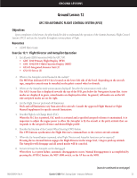
GROUND LESSONS Ground Lesson 12 GFC 700 AUTOMATIC FLIGHT CONTROL SYSTEM (AFCS) Objectives Upon completion of this lesson, the pilot should be able to understand the operation of the Garmin Automatic Flight Control System (AFCS) and use the Autopilot throughout various phases of flight. Resources • G1000 Pilot's Guide Exercise 12.1: Flight Director and Autopilot Operation 1. List all parts (LRUs) associated with the GFC 700. • GDU 1040 Primary Flight Display (PFD) • GDU 1042/1043 Multi Function Display (MFD) • GIA 63 Integrated Avionics Unit (2) • GSA 81 Servos (3) 2. Where is the Autopilot control located in the cockpit? The MFD has dedicated AFCS keys located on the lower left side of the bezel. Depending on the aircraft type, autopilot controls may be installed on the pilot's control wheel or throttle. 3. Where are the Autopilot mode annunciations displayed? Describe the annunciation mode color. The AFCS Status Bar is displayed towards the top of the PFD, just below the Navigation Status Bar. Active modes are displayed in green, armed modes are displayed in white. In general, roll modes are on the left side and pitch modes are on the right. 4. List the Flight Director pitch and roll limitations. Pitch and roll limitations vary from aircraft to aircraft. Consult the approved Flight Manual or Flight Manual Supplement for specific aircraft limitations. 5. Describe Flight Level Change Mode (FLC). When the FLC key is pressed, FLC mode is activated and a specified airspeed reference is maintained. It is important to adjust the engine power to allow the Autopilot to fly the aircraft at the pitch attitude that corresponds to the airspeed reference and desired flight profile. 6. Describe the function of the Control Wheel Steering (CWS) button. The CWS buttons synchronizes the Flight Director's command bars to the current aircraft attitude. 7. When the Go-Around button is pressed, what Flight Director and Autopilot functions can be expected? Pressing the Go-Around button engages the Flight Director in the wings level, 7-degree pitch up attitude. The Autopilot will disengage and all armed modes will be canceled. 8. List several ways the Autopilot can be disengaged. When there is a system failure, automatic disengagement occurs. Manual disengagement is accomplished by pressing the AP DISC button, the MET ARM switch, or the AP key on the MFD. 190-00368-04 Rev. A (exercise continued on next page) Garmin G1000 Pilot's Training Guide - Instructor's Reference 23
-
 1
1 -
2
-
3
-
4
-
5
-
6
-
7
-
8
-
9
-
10
-
11
-
12
-
13
-
14
-
15
-
16
-
17
-
18
-
19
-
20
-
21
-
22
-
23
-
 24
24 -
 25
25 -
 26
26 -
 27
27 -
 28
28 -
 29
29 -
 30
30 -
 31
31 -
 32
32 -
 33
33 -
 34
34 -
35
-
36
-
37
-
38
-
39
-
40
-
41
-
42
-
43
-
44
-
45
-
46
-
47
-
48
-
49
-
50
-
51
-
52
-
53
-
54
 |
 |