Gateway MX6750h 8511340 - Gateway Notebook Hardware Reference - Page 50
Step 15, Step 20
 |
View all Gateway MX6750h manuals
Add to My Manuals
Save this manual to your list of manuals |
Page 50 highlights
CHAPTER 3: Maintaining and Upgrading Your Notebook www.gateway.com 14 Gently lift the back edge of the keyboard. ■ If the keyboard does not lift, go to Step 15. ■ If the keyboard lifts, go to Step 20. 15 Close the LCD panel, turn your notebook over so the bottom is facing up, then loosen the six memory bay cover screws (these screws cannot be removed). Screws 16 Use the thumb notch to lift the memory bay cover, then remove it. Be careful not to break off the tabs located on the end of the cover opposite of the thumb notch. 17 Loosen the mini-PCI bay cover screw (this screw cannot be removed), then remove the mini-PCI bay cover. 46
-
 1
1 -
2
-
3
-
4
-
5
-
6
-
7
-
8
-
9
-
10
-
11
-
12
-
13
-
14
-
15
-
16
-
17
-
18
-
19
-
20
-
21
-
22
-
23
-
24
-
25
-
26
-
27
-
28
-
29
-
30
-
31
-
32
-
33
-
34
-
35
-
36
-
37
-
38
-
39
-
40
-
41
-
42
-
43
-
44
-
 45
45 -
 46
46 -
 47
47 -
 48
48 -
 49
49 -
 50
50 -
 51
51 -
 52
52 -
 53
53 -
 54
54 -
 55
55 -
56
-
57
-
58
-
59
-
60
-
61
-
62
-
63
-
64
-
65
-
66
-
67
-
68
-
69
-
70
-
71
-
72
 |
 |
CHAPTER 3: Maintaining and Upgrading Your Notebook
www.gateway.com
46
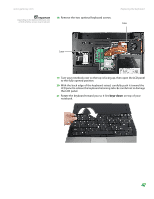
14
Gently lift the back edge of the keyboard.
■
If the keyboard does not lift, go to
Step 15
.
■
If the keyboard lifts, go to
Step 20
.
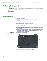
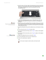
15
Close the LCD panel, turn your notebook over so the bottom is facing up,
then loosen the six memory bay cover screws (these screws cannot be
removed).
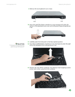
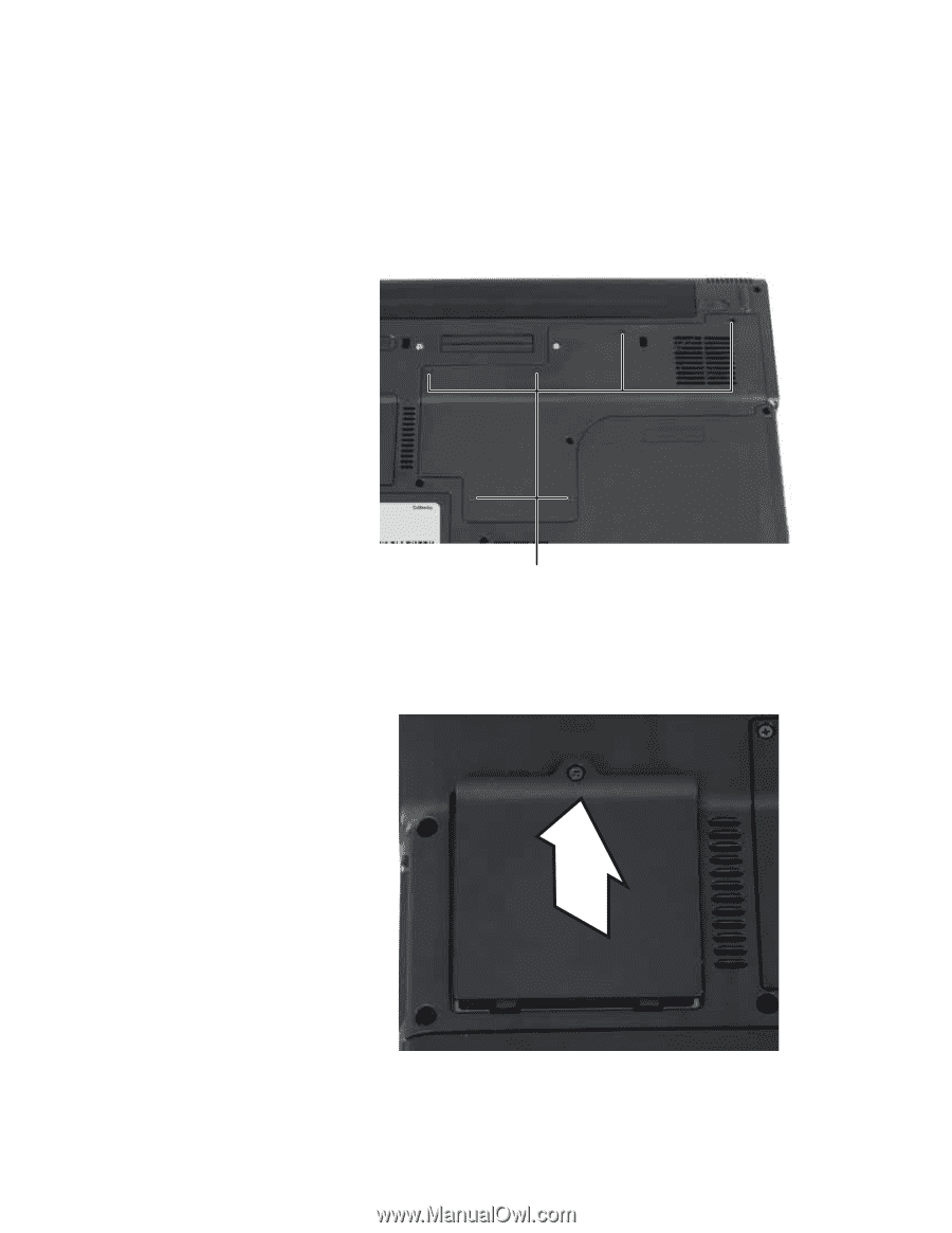
16
Use the thumb notch to lift the memory bay cover, then remove it. Be
careful not to break off the tabs located on the end of the cover opposite
of the thumb notch.
17
Loosen the mini-PCI bay cover screw (this screw cannot be removed), then
remove the mini-PCI bay cover.
Screws