Gigabyte GA-990FXA-UD3 Manual - Page 20
Back Panel Connectors - raid
 |
View all Gigabyte GA-990FXA-UD3 manuals
Add to My Manuals
Save this manual to your list of manuals |
Page 20 highlights
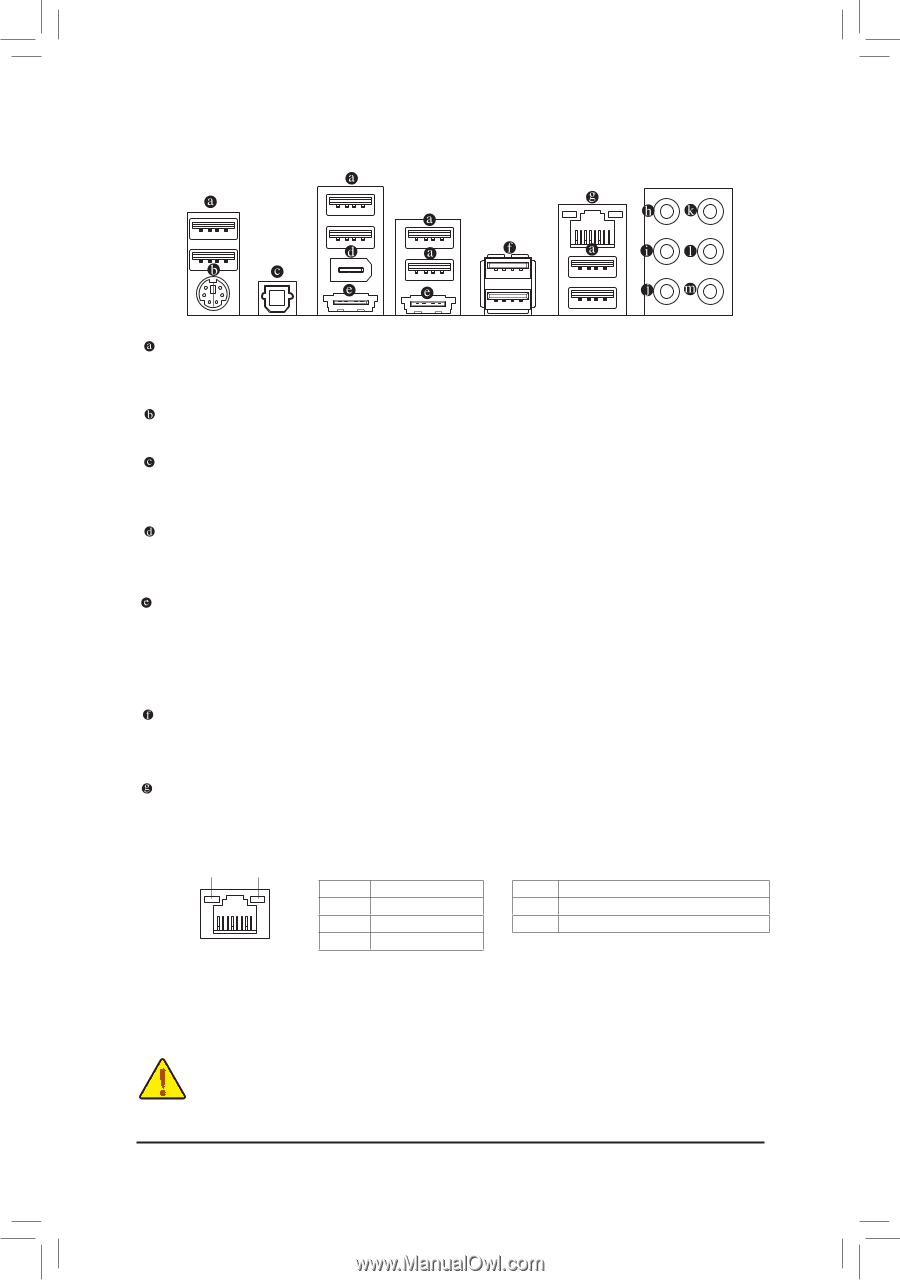
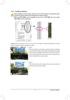
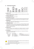
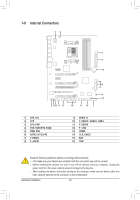
1-7 Back Panel Connectors USB 2.0/1.1 Port The USB port supports the USB 2.0/1.1 specification. Use this port for USB devices such as a USB keyboard/mouse, USB printer, USB flash drive and etc. PS/2 Keyboard/Mouse Port Use this port to connect a PS/2 mouse or keyboard. Optical S/PDIF Out Connector This connector provides digital audio out to an external audio system that supports digital optical audio. Before using this feature, ensure that your audio system provides an optical digital audio in connector. IEEE 1394a Port The IEEE 1394 port supports the IEEE 1394a specification, featuring high speed, high bandwidth and hotplug capabilities. Use this port for an IEEE 1394a device. eSATA 6Gb/s Connector The eSATA 6Gb/s port conforms to SATA 6Gb/s standard and is compatible with SATA 3Gb/s and SATA 1.5Gb/s standards. Use the port to connect an external SATA device or a SATA port multiplier. The Marvell 88SE9172 chip supports RAID function. Refer to Chapter 5, "Configuring SATA Hard Drive(s)," for instructions on configuring a RAID array. USB 3.0/2.0 Port The USB 3.0 port supports the USB 3.0 specification and is compatible to the USB 2.0/1.1 specification. Use this port for USB devices such as a USB keyboard/mouse, USB printer, USB flash drive and etc. RJ-45 LAN Port The Gigabit Ethernet LAN port provides Internet connection at up to 1 Gbps data rate. The following escribes the states of the LAN port LEDs. Connection/ Speed LED Activity LED LAN Port Connection/Speed LED: State Orange Green Off Description 1 Gbps data rate 100 Mbps data rate 10 Mbps data rate Activity LED: State Description Blinking Data transmission or receiving is occurring Off No data transmission or receiving is occurring •• When removing the cable connected to a back panel connector, first remove the cable from your device and then remove it from the motherboard. •• When removing the cable, pull it straight out from the connector. Do not rock it side to side to prevent an electrical short inside the cable connector. Hardware Installation - 20 -
-
 1
1 -
2
-
3
-
4
-
5
-
6
-
7
-
8
-
9
-
10
-
11
-
12
-
13
-
14
-
 15
15 -
 16
16 -
 17
17 -
 18
18 -
 19
19 -
 20
20 -
 21
21 -
 22
22 -
 23
23 -
 24
24 -
 25
25 -
26
-
27
-
28
-
29
-
30
-
31
-
32
-
33
-
34
-
35
-
36
-
37
-
38
-
39
-
40
-
41
-
42
-
43
-
44
-
45
-
46
-
47
-
48
-
49
-
50
-
51
-
52
-
53
-
54
-
55
-
56
-
57
-
58
-
59
-
60
-
61
-
62
-
63
-
64
-
65
-
66
-
67
-
68
-
69
-
70
-
71
-
72
-
73
-
74
-
75
-
76
-
77
-
78
-
79
-
80
-
81
-
82
-
83
-
84
-
85
-
86
-
87
-
88
-
89
-
90
-
91
-
92
-
93
-
94
-
95
-
96
-
97
-
98
-
99
-
100
-
101
-
102
-
103
-
104
-
105
-
106
-
107
-
108
-
109
-
110
-
111
-
112
 |
 |