Gigabyte GA-Z77X-UD5H Manual - Page 24
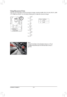
Voltage Measurement Points, Connect the red lead of the multimeter to the pin 1 +12V - pcie 3 0
 |
View all Gigabyte GA-Z77X-UD5H manuals
Add to My Manuals
Save this manual to your list of manuals |
Page 24 highlights
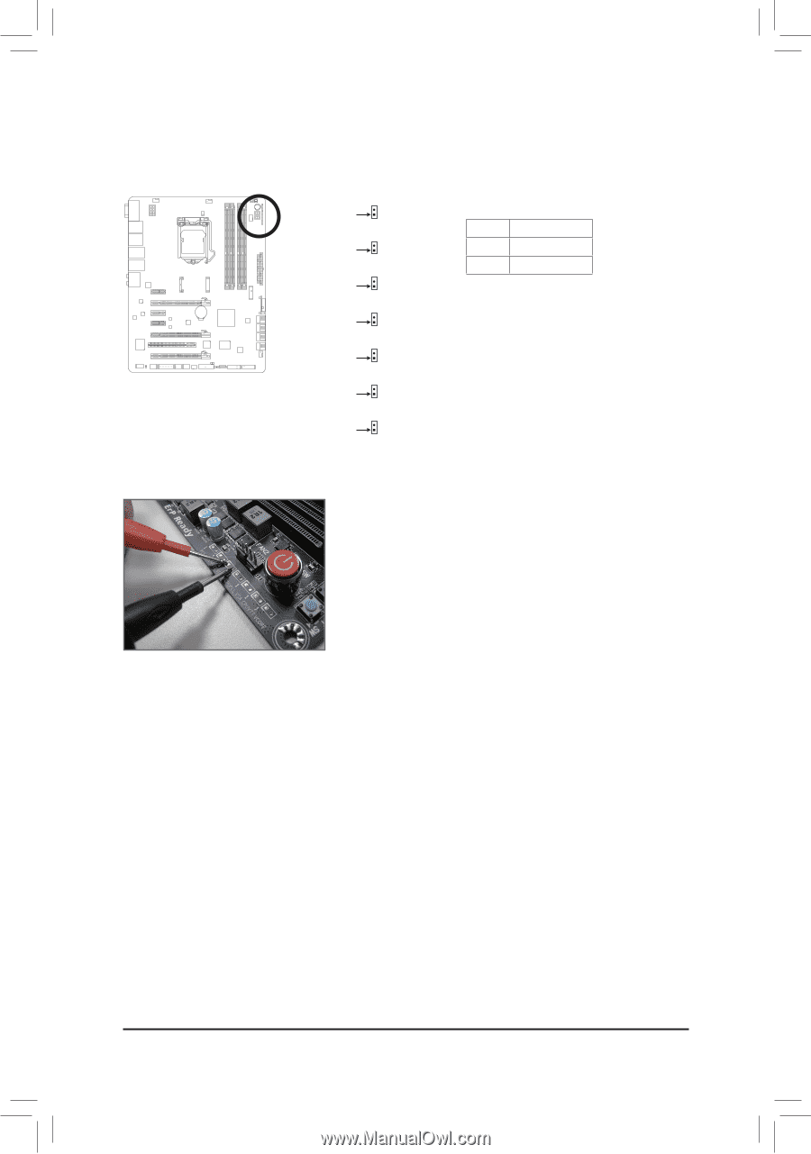
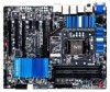
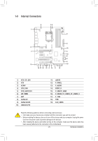
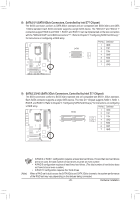
DIP 1 23 DIP 1 23 DIP 1 1 23 DIP 1 1 23 DIP 1 1 23 DIP 1 1 23 DIP 1 TPM w/housing TPM w/housing TPM w/housing Voltage Measurement PointsTwP/hMousing VoltDagBe_PmOeRasTurement module(X58A-OC) VoltDagBe_PmOeRasTurement module(X58A-OC) PCIe power connector (SATA)(X58A-OC) VoltDagBe_PmOeRasTurement module(X58A-OC) PCIe power connector (SATA)(X58A-OC) VoltDagBe_PmOeRasTurement module(X58A-OC) PCIe power connector (SATA)(X58A-OC) DIP 1 23 1 DIP 1 23 1 DIP 1 23 1 D 12 1 1 1 1 1 BIOS Switcher (X58A-OC) PWM1 SDwIPitch (X58A-OC) BIOS S1w2it3cher (X58A-OC) PWM1 SDwIPitch (X58A-OC) BIOS S1w2it3cher (X58A-OC) PWM1 SDwIPitch (X58A-OC) BIOS S1w2it3cher (X58A-OC) PWM1 SDwIPitch (X58A-OC) DIP 1 23 DIP 1 23 DIP 1 23 DIP 1 23 DIP 1 23 1 Users can use a multimeter to measure component voltages, includinVgoltaVgeCmOeasRureEm,enCt mPodUuleV(X5T8AT-,OVC)SA, CPU1 P2 3LL, DDR VTT, VDIMM, and PCHIO. You TPM canw/ehomusipngloy following way to measure PcCoIempopweor cnoennnecttovr (oSAlTtaA)g(Xe58sA-.OC) PWM SDwIPitch (X58A-OC) DIP 1 23 DIP 1 23 TPM w/housing Voltage measurement VCORE points(G1.SniperV3o)ltaPgCeIempeoawsuerrecmBoeInOnnStemcStoowdritu(cSlheAe(XTrA5(S8)(AWX-54O8)CA)-OC) Pin 1 Voltage measurement CPUVTT points(G1.Sniper 3P) inPCNIeopo.wer cDBoIneOnSfeicnStowitriit(coShnAeTrA(S)(WX548)A-OC) Pin 1 1 +12V DIP 1 23 1 23 PWM SDwIPitch (X58A-OC) 1 23 DIP 1 23 DIP 1 23 DIP 1 23 2 GND Voltage measurement points(G1.Sniper 3) VSA BIOS Switcher (SW4) PCIe power connector (SATA)(X58A-OC) Pin 1 Voltage measurement points(G1.Sniper 3) CPUPLL BIOS Switcher (SW4) Pin 1 Voltage measurement points(G1.Sniper 3) DDRVTT BIOS Switcher (SW4) Pin 1 Voltage measurement points(G1.Sniper 3) VDIMM BIOS Switcher (SW4) Pin 1 Voltage measurement points(G1.Sniper 3) PCHIO BIOS Switcher (SW4) Pin 1 M_SATA M_SATA M_SATA M_SATA M_SATA Steps: Connect the red lead of the multimeter to the pin 1 (+12V) of a voltage measurement point and the black lead to the pin 2 (ground). Hardware Installation - 24 -
-
 1
1 -
2
-
3
-
4
-
5
-
6
-
7
-
8
-
9
-
10
-
11
-
12
-
13
-
14
-
15
-
16
-
17
-
18
-
 19
19 -
 20
20 -
 21
21 -
 22
22 -
 23
23 -
 24
24 -
 25
25 -
 26
26 -
 27
27 -
 28
28 -
 29
29 -
30
-
31
-
32
-
33
-
34
-
35
-
36
-
37
-
38
-
39
-
40
-
41
-
42
-
43
-
44
-
45
-
46
-
47
-
48
-
49
-
50
-
51
-
52
-
53
-
54
-
55
-
56
-
57
-
58
-
59
-
60
-
61
-
62
-
63
-
64
-
65
-
66
-
67
-
68
-
69
-
70
-
71
-
72
-
73
-
74
-
75
-
76
-
77
-
78
-
79
-
80
-
81
-
82
-
83
-
84
-
85
-
86
-
87
-
88
-
89
-
90
-
91
-
92
-
93
-
94
-
95
-
96
-
97
-
98
-
99
-
100
-
101
-
102
-
103
-
104
-
105
-
106
-
107
-
108
-
109
-
110
-
111
-
112
-
113
-
114
-
115
-
116
-
117
-
118
-
119
-
120
-
121
-
122
-
123
-
124
-
125
-
126
-
127
-
128
 |
 |