Gigabyte GA-Z77X-UD5H Manual - Page 27
CPU_FAN/SYS_FAN1/SYS_FAN2/SYS_FAN3/SYS_FAN4 Fan Headers, ATX4P PCIe Power Connector
 |
View all Gigabyte GA-Z77X-UD5H manuals
Add to My Manuals
Save this manual to your list of manuals |
Page 27 highlights
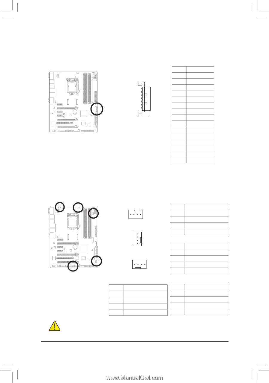
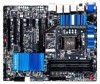
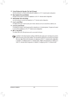
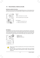
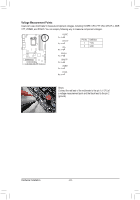
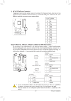
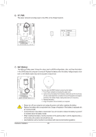
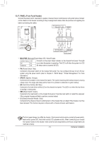
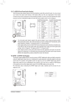
BIOS Switcher (X58A-OC) 1 M_SATA F_PANEL(NH) PWM Switch (X58A-OC) DIP 1 23 PCIe power connector (SATA)(X58A-OC) DIP 1 23 1 DIP 1 23 1 3) ATX4P (PCIe Power Connector) The power connector provide auxiliary powDeIPr to the onboard PCI Express x16 slots. When two or more graphics cards are installed, we recomme1n2d3 that you connect the SATA power cable(s) from the power supply to the ATX4P con1 nector to ensure system stability. Voltage measurement module(X58A-OC) DB_PORT Pin No. Definition 1 NC 2 NC BIOS Switcher (SW4) 1 3 NC 4 GND 5 GND 6 GND 15 7 VCC 8 VCC 9 VCC 10 GND 11 GND 12 GND 13 +12V 14 +12V 15 +12V F_AUDIO(H) Voltage measurement points(G1.Sniper 3) F_USB30 TPM w/housing 4/5) CPU_FAN/SYS_FAN1/SYS_FAN2/SYS_FAN3/SYS_FAN4 (Fan Headers) All fan headers on this motherboard are 4-pin. Most fan headers possess a foolproof insertion design. When connecting a fan cable, be sure to connect it in the correct orientation (the black connector wire is the ground wire). The speed control function requires the use of a fan with fan speed control design. For optimum heat dissipation, it is recommended that a system fan be installed inside the chassis. CPU_FAN: Pin No. Definition 1 CPU_FAN 1 GND 2 +12V /Speed Control 3 Sense 4 Speed Control 1 SYS_FAN1/SYS_FAN2 1 SYS_FAN3/SYS_FAN4 SYS_FAN1: Pin No. Definition 1 GND 2 +12V /Speed Control 3 Sense 4 VCC SYS_FAN2/3: Pin No. Definition 1 GND 2 +12V 3 Sense 4 Speed Control SYS_FAN4: Pin No. Definition 1 GND 2 +12V 3 Sense 4 Reserve •• Be sure to connect fan cables to the fan headers to prevent your CPU and system from overheating. Overheating may result in damage to the CPU or the system may hang. •• These fan headers are not configuration jumper blocks. Do not place a jumper cap on the headers. - 27 - Hardware Installation
-
 1
1 -
2
-
3
-
4
-
5
-
6
-
7
-
8
-
9
-
10
-
11
-
12
-
13
-
14
-
15
-
16
-
17
-
18
-
19
-
20
-
21
-
 22
22 -
 23
23 -
 24
24 -
 25
25 -
 26
26 -
 27
27 -
 28
28 -
 29
29 -
 30
30 -
 31
31 -
 32
32 -
33
-
34
-
35
-
36
-
37
-
38
-
39
-
40
-
41
-
42
-
43
-
44
-
45
-
46
-
47
-
48
-
49
-
50
-
51
-
52
-
53
-
54
-
55
-
56
-
57
-
58
-
59
-
60
-
61
-
62
-
63
-
64
-
65
-
66
-
67
-
68
-
69
-
70
-
71
-
72
-
73
-
74
-
75
-
76
-
77
-
78
-
79
-
80
-
81
-
82
-
83
-
84
-
85
-
86
-
87
-
88
-
89
-
90
-
91
-
92
-
93
-
94
-
95
-
96
-
97
-
98
-
99
-
100
-
101
-
102
-
103
-
104
-
105
-
106
-
107
-
108
-
109
-
110
-
111
-
112
-
113
-
114
-
115
-
116
-
117
-
118
-
119
-
120
-
121
-
122
-
123
-
124
-
125
-
126
-
127
-
128
 |
 |