Gigabyte GA-Z77X-UD5H Manual - Page 34
TPM Trusted Platform Module Header, F_1394 IEEE 1394a Header, To connect an IEEE 1394a device
 |
View all Gigabyte GA-Z77X-UD5H manuals
Add to My Manuals
Save this manual to your list of manuals |
Page 34 highlights
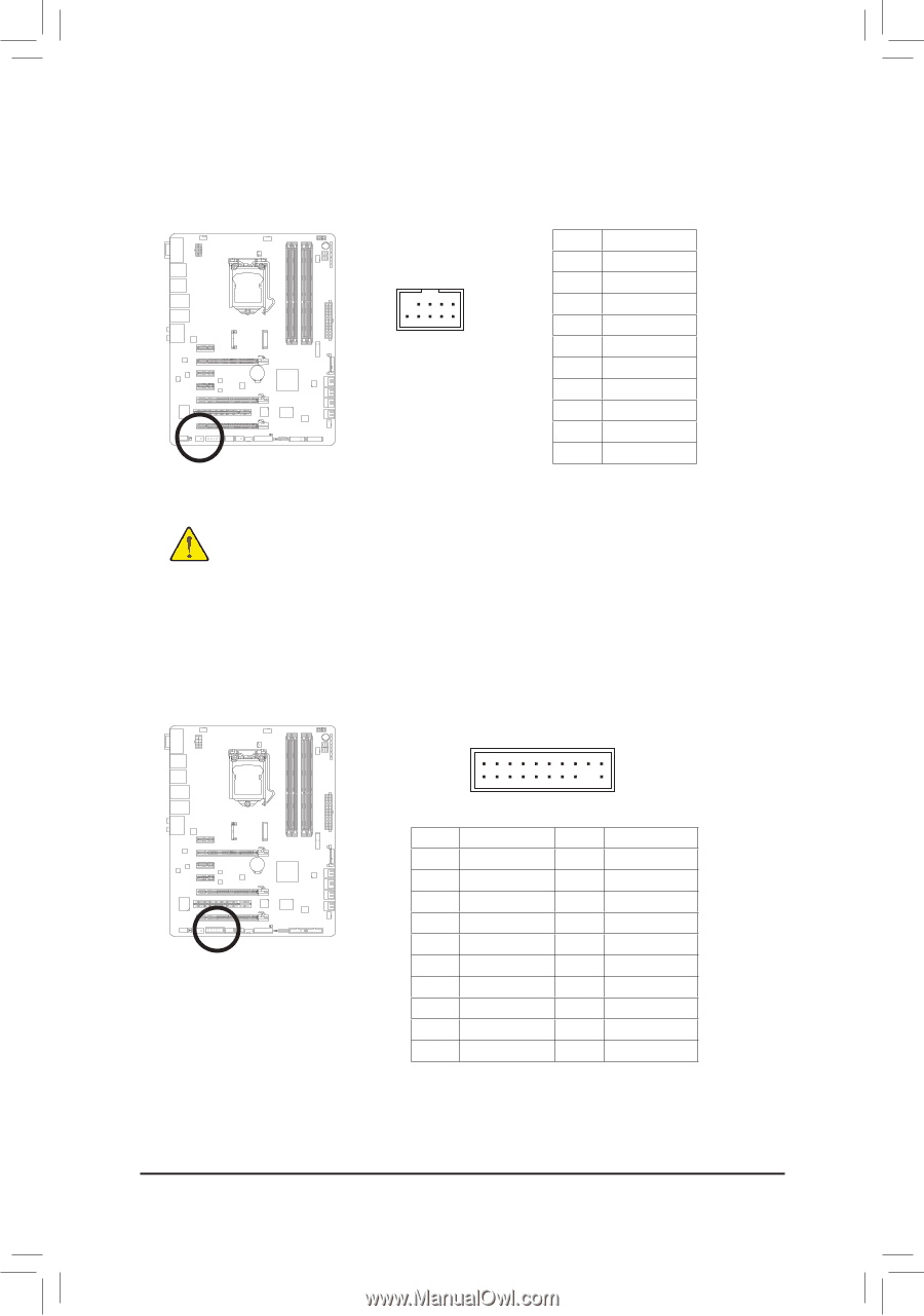
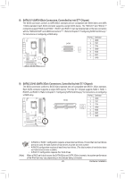
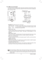
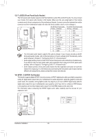
17) F_1394 (IEEE 1394a Header) The header conforms to IEEE 1394a specification. The IEEE 1394a header can provide one IEEE 1394a port via an optional IEEE 1394a bracket. For purchasing the optional IEEE 1394a bracket, please contact the local dealer. 9 1 10 2 F_USB30 Pin No. 1 2 3 4 5 6 7 8 9 10 Definition TPA+ TPAGND GND TPB+ TPBPower (12V) Power (12V) No Pin F_AUDIO(H) GND •• Do not plug the USB bracket cable into the IEEE 1394a header. •• Prior to installing the IEEE 1394a bracket, be sure to turn off your computer and unplug the power cord from the power outlet to prevent damage to the IEEE 1394a bracket. •• To connect an IEEE 1394a device, attach one end of the device cable to your computer and then attach the other end of the cable to the IEEE 1394a device. Ensure that the cable is securely connected. DB_PORT 18) TPM (Trusted Platform Module Header) You may connect a TPM (Trusted Platform Module) to this header. BIOS Switc 1 1 19 TPM w/housing 20 1 Voltage measurement module(X58A-OC) 2 Pin No. 1 2 3 4 5 6 7 8 9 10 Definition Pin No. Definition LCLK GND 11 LAD0 12 GND PCIe power connector (SATA)(X58A-OC) LFRAME 13 NC No Pin 14 ID LRESET 15 SB3V NC 16 SERIRQ LAD3 17 GND LAD2 18 NC VCC3 19 NC LAD1 20 SUSCLK Voltage measurement points(G1.Sniper 3) BIOS Switcher (SW4) PWM Swi DIP 1 23 DIP 1 Hardware Installation - 34 -
-
 1
1 -
2
-
3
-
4
-
5
-
6
-
7
-
8
-
9
-
10
-
11
-
12
-
13
-
14
-
15
-
16
-
17
-
18
-
19
-
20
-
21
-
22
-
23
-
24
-
25
-
26
-
27
-
28
-
 29
29 -
 30
30 -
 31
31 -
 32
32 -
 33
33 -
 34
34 -
 35
35 -
 36
36 -
 37
37 -
 38
38 -
 39
39 -
40
-
41
-
42
-
43
-
44
-
45
-
46
-
47
-
48
-
49
-
50
-
51
-
52
-
53
-
54
-
55
-
56
-
57
-
58
-
59
-
60
-
61
-
62
-
63
-
64
-
65
-
66
-
67
-
68
-
69
-
70
-
71
-
72
-
73
-
74
-
75
-
76
-
77
-
78
-
79
-
80
-
81
-
82
-
83
-
84
-
85
-
86
-
87
-
88
-
89
-
90
-
91
-
92
-
93
-
94
-
95
-
96
-
97
-
98
-
99
-
100
-
101
-
102
-
103
-
104
-
105
-
106
-
107
-
108
-
109
-
110
-
111
-
112
-
113
-
114
-
115
-
116
-
117
-
118
-
119
-
120
-
121
-
122
-
123
-
124
-
125
-
126
-
127
-
128
 |
 |