HealthRider 230 English Manual - Page 10
Cable Assembly
 |
View all HealthRider 230 manuals
Add to My Manuals
Save this manual to your list of manuals |
Page 10 highlights
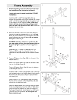
17. Leg Lever Assembly. Attach a Bumper (40) to the 17 Seat Frame (7) with a #8 x 1Ó Screw (78). 7 Press a 2Ó Square Inner Cap (28) into the indicated end of the Leg Lever (41). Lubricate a 3/8Ó x 3Ó Bolt (53). Attach the Leg Lever (41) to the Seat Frame (7) with the 3/8Ó x 3Ó Bolt and a 3/8Ó Nylon Jamnut (63). 40 78 53 Lubricate Cable Assembly 18 18. Locate and open the parts bag labeled ÒCable Assembly and Pulleys.Ó For Cable identification and routing during steps 18Ñ39, refer to the Cable Diagram and Cable ID Chart on page 19. Identify the Low Cable (72). It is approximately 176Ó long and it has a ball on one end and a bolt on the other. Route the end of the Low Cable (72) with the ball through the bracket on the Weight Base (5) as shown. Attach the 3 1/2Ó Pulley (24) to the bracket with a 3/8Ó x 2Ó Bolt (54) and a 3/8Ó Nylon Locknut (50). 24 50 Bracket 63 28 41 54 72 5 19. Wrap the Low Cable (72) around a 3 1/2Ó Pulley (24) 19 in the direction shown. Attach the 3 1/2Ó Pulley (24) and a Cable Trap (25) to 2 the welded tube on the Weight Upright (2) with a 3/8Ó x 3 3/4Ó Bolt (59) and a 3/8Ó Nylon Locknut (50). Make sure the Cable Trap is oriented as shown. 24 50 Welded 25 Tube 10 59 72
-
 1
1 -
2
-
3
-
4
-
 5
5 -
 6
6 -
 7
7 -
 8
8 -
 9
9 -
 10
10 -
 11
11 -
 12
12 -
 13
13 -
 14
14 -
 15
15 -
16
-
17
-
18
-
19
-
20
-
21
-
22
-
23
-
24
-
25
-
26
-
27
-
28
-
29
 |
 |
