HealthRider 230 English Manual - Page 5
Frame Assembly
 |
View all HealthRider 230 manuals
Add to My Manuals
Save this manual to your list of manuals |
Page 5 highlights
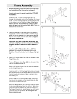
Frame Assembly 1 1. Before beginning, make sure that you have read and understood the information on page 4. Locate and open the parts bag labeled ÒFRAME ASSEMBLY.Ó Insert four 3/8Ó x 2 3/4Ó Carriage Bolts (45) up through the indicated holes in the Stabilizer (4). Insert a 3/8Ó x 3 1/2Ó Carriage Bolt (62) up through the hole in the sidearm on the Stabilizer. Note: If the Bolts 62 tend to fall out, secure them by putting a small piece of tape over the head of each Bolt. Place the Stabilizer flat on the floor. 2 2. Place the bracket on the lower end of the Support Upright (3) over the indicated 3/8Ó x 2 3/4Ó Carriage Bolts (45) in the Stabilizer (4). Hand tighten two 3/8Ó Nylon Locknuts (50) onto the Bolts. Do not tighten the Nylon Locknuts yet. CAUTION: Until step 3 has been performed, the unit can easily tip over. Have one person hold the Support Upright in position or lean it against a wall. Insert two 3/8Ó x 3Ó Bolts (53) with two 3/8Ó Flat Washers (55) through the indicated holes in the Stabilizer (4) and the bracket on the Support Upright (3). 3. Press a 2Ó Square Inner Cap (28) into the end of the Weight Base (5). Press a 2Ó Square Inner Cap (28) into the end of the riser on the Weight Base (5). Press a 2Ó Square Cover Cap (33) onto the sidearm on the Weight Base (5). Insert two 3/8Ó x 2 3/4Ó Carriage Bolts (45) up through the indicated holes in the Weight Base (5) and secure the bolt heads with pieces of tape to prevent them from falling out. Insert a 3/8Ó x 3 1/2Ó Carriage Bolt (62) up through the hole in the sidearm on the Weight Base (5) and secure the bolt head with tape. Place the Weight Base (5) on the floor with the holes in the mounting bracket over the 3/8Ó x 3Ó Bolts (53) going through the Stabilizer (4) and the bracket on the Support Upright (3). Hand tighten two 3/8Ó Nylon Locknuts (50) onto the Bolts. Do not tighten the Nylon Locknuts yet. 5 3 50 53 55 3 50 3 53 4 45 45 50 55 53 4 Bracket 45 4 33 62 28 5 28 45
-
 1
1 -
 2
2 -
 3
3 -
 4
4 -
 5
5 -
 6
6 -
 7
7 -
 8
8 -
 9
9 -
 10
10 -
 11
11 -
12
-
13
-
14
-
15
-
16
-
17
-
18
-
19
-
20
-
21
-
22
-
23
-
24
-
25
-
26
-
27
-
28
-
29
 |
 |
