HealthRider 230 English Manual - Page 11
Make sure the Low Cable
 |
View all HealthRider 230 manuals
Add to My Manuals
Save this manual to your list of manuals |
Page 11 highlights
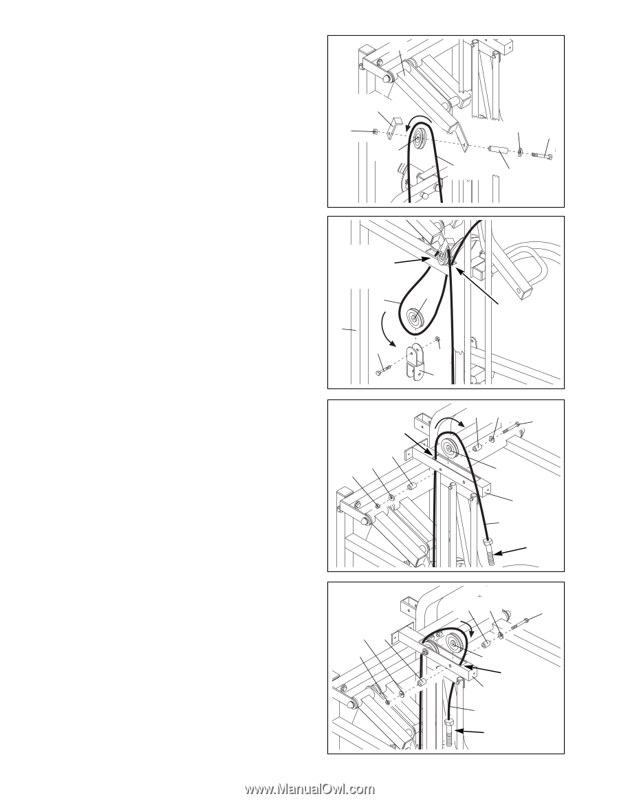
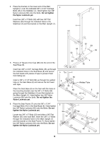
20. Wrap the Low Cable (72) around a 3 1/2Ó Pulley (24) in the direction shown. Attach the 3 1/2Ó Pulley (24) and a Cable Trap (25) to the bracket on the Press Adjustment Frame (14) with a 3/8Ó x 3Ó Bolt (53), a 3/8Ó Flat Washer (55), a 5/8Ó x 1 1/4Ó Bushing (91) and a 3/8Ó Nylon Jamnut (63). Make sure the Cable Trap is oriented as shown. 20 14 25 63 24 55 53 72 91 21. Route the Low Cable (72) through the indicated slot in the Support Upright (3) from above. Locate the Small Pulley Frame (22) and remove both of the pre-assembled 3 1/2Ó Pulleys (24). Wrap the Low Cable (72) around a 3 1/2Ó Pulley (24) in the direction shown. Attach the 3 1/2Ó Pulley (24) to the top half of the Small Pulley Frame (22) with a 3/8Ó x 2Ó Bolt (54) and a 3/8Ó Nylon Locknut (50). Note: The Pulley Frame must be oriented as shown. Route the Low Cable (72) through the indicated slot in the Support Upright (3) from below. 21 Route Cable Through Slot From Above 72 3 54 22. Feed the bolt at the end of the Low Cable (72) through the indicated slot in the Weight Upright (2) from below. 22 Welded Rod Attach a 3 1/2Ó Pulley (24) inside the slot in the Weight Upright (2). To do this, slide a 3/8Ó Flat Washer (55) and a 5/8Ó x 1/2Ó Bushing (85) onto a 3/8Ó x 2 3/4Ó Bolt (47). Insert the Pulley into the slot in the Upright and hold it in position while pushing the Bolt through the hole in the Upright and the Pulley. Slide a 5/8Ó x 1/2Ó Bushing (85) and a 3/8Ó Flat Washer (55) onto the Bolt and secure it with a 3/8Ó Nylon Locknut (50). Make sure the Low Cable (72) is wrapped around the Pulley in the direction shown, and that it is between the welded rod inside the Upright and the Pulley. 23. Feed the end of the Low Cable (72) through the indicated slot in the Weight Upright (2) from above. Wrap the Low Cable (72) around a 3 1/2Ó Pulley (24). Attach the 3 1/2Ó Pulley inside the slot in the Weight Upright (2) with a 3/8Ó x 2 3/4Ó Bolt (47), two 3/8Ó Flat Washers (55), two 5/8Ó x 1/2Ó Bushings (85) and a 3/8Ó Nylon Locknut (50). Make sure the Low Cable is wrapped around the Pulley in the direction shown, and that it is between the welded rod inside the Upright and the Pulley. 85 55 50 23 55 85 50 24 50 22 Route Cable Through Slot From Below 85 55 47 24 2 72 Bolt 85 55 47 24 Welded Rod 2 72 Bolt 11
-
 1
1 -
2
-
3
-
4
-
5
-
 6
6 -
 7
7 -
 8
8 -
 9
9 -
 10
10 -
 11
11 -
 12
12 -
 13
13 -
 14
14 -
 15
15 -
 16
16 -
17
-
18
-
19
-
20
-
21
-
22
-
23
-
24
-
25
-
26
-
27
-
28
-
29
 |
 |