HP 3PAR StoreServ 7450 2-node HP 3PAR StoreServ 7450 Storage Troubleshooting G - Page 6
Identifying Storage System Components, Understanding Component Numbering, Drive Enclosures
 |
View all HP 3PAR StoreServ 7450 2-node manuals
Add to My Manuals
Save this manual to your list of manuals |
Page 6 highlights
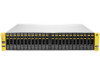
1 Identifying Storage System Components NOTE: The illustrations in this chapter are used examples only and may not reflect your storage system configuration. Understanding Component Numbering Due to the large number of possible configurations, component placement and internal cabling is standardized to simplify installation and maintenance. System components are placed in the rack according to the principles outlined in this chapter, and are numbered according to their order and location in the cabinet. The storage system includes the following types of drive and node enclosures: • The HP M6710 Drive Enclosure (2U24) holds up to 24, 2.5 inch small form factor (SFF) Serial Attached SCSI (SAS) Solid State Disks (SSD) disk drives arranged vertically in a single row on the front of the enclosure. Two 580 W power cooling modules (PCMs) and two I/O modules are located on the back of the enclosure. • The HP M6720 Drive Enclosure (4U24) holds up to 24, 3.5 inch large form factor (LFF) SAS SSD disk drives, arranged horizontally with four columns of six disk drives located on the front of the enclosure. Two 580 W PCMs and two I/O modules are located on the back of the enclosure. NOTE: The SSDs have a limited number of writes that occurs before reaching its write-endurance limit. The manufacturer generally sets a high write-endurance limit to endure degradation caused by various input/output processes and workloads over a period of time. The HP 3PAR StoreServ Storage system tracks all writes to the SSDs and reports the total percentage of write-endurance limit used by system. The constant performance monitoring provides the ability to early detect any SSDs approaching its limit and replace them before they become fully degraded. The SSD reaches its maximum usage limit when it exceeds the write-endurance limit. Any SSDs exceeding the maximum usage limit during the product warranty period will not be repaired or replaced under HP Support contracts. NOTE: In the HP 3PAR Management Console or CLI, the enclosures are displayed as DCS2 for 2U24 (M6710) , DCS1 (M6720) for 4U24, and DCN1 for a node enclosure. Drive Enclosures The maximum number of supported drive enclosures depends on the model and the number of nodes. Disk Drive Numbering The disk drives are mounted on a drive carrier and reside at the front of the enclosures. There are two types of disk drives: • Vertical, 2.5 inch SFF disks. The 2U24 enclosure numbering starts with 0 on the left and ends with 23 on the right. See Figure 1 (page 7). • Horizontal, 3.5 inch LFF disks. The 4U24 enclosure are numbered with 0 on the lower left to 23 on the upper right, with six rows of four. See Figure 2 (page 7). 6 Identifying Storage System Components
-
 1
1 -
 2
2 -
 3
3 -
 4
4 -
 5
5 -
 6
6 -
 7
7 -
 8
8 -
 9
9 -
 10
10 -
 11
11 -
 12
12 -
13
-
14
-
15
-
16
-
17
-
18
-
19
-
20
-
21
-
22
-
23
-
24
-
25
-
26
-
27
-
28
-
29
-
30
-
31
-
32
-
33
-
34
-
35
-
36
-
37
-
38
-
39
-
40
-
41
-
42
-
43
-
44
-
45
-
46
-
47
-
48
-
49
-
50
-
51
-
52
-
53
-
54
-
55
-
56
-
57
-
58
-
59
-
60
-
61
-
62
-
63
-
64
-
65
-
66
-
67
 |
 |
