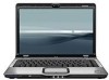
HP Dv2910us HP Pavilion dv2500 and dv2700 Notebook PC - Maintenance and Servic
HP Dv2910us - Pavilion Entertainment - Core 2 Duo 1.83 GHz Manual
 |
UPC - 884420154242
View all HP Dv2910us manuals
Add to My Manuals
Save this manual to your list of manuals |
HP Dv2910us manual content summary:
- HP Dv2910us | HP Pavilion dv2500 and dv2700 Notebook PC - Maintenance and Servic - Page 1
HP Pavilion dv2500 and dv2700 Notebook PC Maintenance and Service Guide - HP Dv2910us | HP Pavilion dv2500 and dv2700 Notebook PC - Maintenance and Servic - Page 2
of Advanced Micro Devices, Inc. Bluetooth is a trademark services. Nothing herein should be construed as constituting an additional warranty. HP shall not be liable for technical or editorial errors or omissions contained herein. Fourth Edition: December 2007 First Edition: April 2007 Document Part - HP Dv2910us | HP Pavilion dv2500 and dv2700 Notebook PC - Maintenance and Servic - Page 3
computer air vents. Use the computer only on a hard, flat surface. Do not allow another hard surface, such as an adjoining optional printer, or a adapter to contact the skin or a soft surface, such as pillows or rugs or clothing, during operation. The computer and the AC adapter comply with the user - HP Dv2910us | HP Pavilion dv2500 and dv2700 Notebook PC - Maintenance and Servic - Page 4
iv Safety warning notice - HP Dv2910us | HP Pavilion dv2500 and dv2700 Notebook PC - Maintenance and Servic - Page 5
components 19 Display assembly components 30 Door/Cover Kit ...32 Cable Kit ...33 Mass storage devices ...34 Miscellaneous parts ...35 Sequential part number listing 37 4 Removal and replacement procedures Preliminary replacement requirements 48 Tools required ...48 Service considerations 48 - HP Dv2910us | HP Pavilion dv2500 and dv2700 Notebook PC - Maintenance and Servic - Page 6
guidelines 51 Equipment guidelines 52 Unknown user password 53 Component replacement procedures 54 Serial number ...54 Computer feet ...55 Battery ...56 Camera module ...57 Display inverter ...59 Hard drive ...61 WLAN module ...65 SIM ...69 RTC battery ...70 Memory module ...71 Optical - HP Dv2910us | HP Pavilion dv2500 and dv2700 Notebook PC - Maintenance and Servic - Page 7
display specifications 123 Hard drive specifications ...124 DVD±RW and CD-RW Super Multi Double-Layer Combo Drive specifications 125 High Definition DVD-ROM and DVD±RW Drive 126 System DMA specifications ...127 System interrupt specifications-Intel processors 128 System interrupt specifications - HP Dv2910us | HP Pavilion dv2500 and dv2700 Notebook PC - Maintenance and Servic - Page 8
Reinstalling preinstalled programs and drivers 163 Reinstalling programs from discs 163 Performing a recovery 164 Recovering from the recovery discs 164 Recovering from the partition on the hard drive 164 Deleting the recovery partition on the hard drive 165 Updating reinstalled software 165 - HP Dv2910us | HP Pavilion dv2500 and dv2700 Notebook PC - Maintenance and Servic - Page 9
Intel processors with discrete graphics subsystem Intel processors with UMA graphics subsystem AMD processors with UMA graphics subsystem HP Pavilion dv2500 and √ dv2700 Notebook PC √ √ Intel® Core™ Duo with 800-MHz front side bus (FSB) T9300 2.50-GHz processor with √ √ 6-MB L2 cache - HP Dv2910us | HP Pavilion dv2500 and dv2700 Notebook PC - Maintenance and Servic - Page 10
Category Chipset Graphics Description Intel processors with discrete graphics subsystem Intel 16 Graphics ● nVidia NB8M GS with 64 MB of dedicated video memory (8M × 32 GDDR3 × 2 PCs) with 128 MB of video memory when system memory is less than 1 GB (64 MB + 64 MB Turbo Cache) ● nVidia NB8M GS with - HP Dv2910us | HP Pavilion dv2500 and dv2700 Notebook PC - Maintenance and Servic - Page 11
Intel processors with discrete graphics subsystem Intel processors with UMA graphics subsystem AMD processors with UMA graphics subsystem System design supports up to 55W GPU requirement. Mobile Intel Graphics Media √ Accelerator X3100 Unified Memory Architecture (UMA) with shared video - HP Dv2910us | HP Pavilion dv2500 and dv2700 Notebook PC - Maintenance and Servic - Page 12
√ √ √ Supports the following drives: √ ● DVD±RW and CD-RW Super Multi Double-Layer Combo Drive with LightScribe ● DVD±RW and CD-RW Super Multi Double-Layer Combo Drive ● DVD-CD/RW Combo Drive √ √ Supports High Definition DVD- √ √ ROM and DVD±RW Drive Supports external USB drive only - HP Dv2910us | HP Pavilion dv2500 and dv2700 Notebook PC - Maintenance and Servic - Page 13
into the display assembly @ 2.4 and 5.0 GHz Intel WLAN + Bluetooth® √ √ Broadcom 4321AGN Wi-Fi √ Adapter (802.11a/b/g/draft-n) + Bluetooth w/2 antennas Broadcom 4321AGN Wi-Fi √ Adapter (802.11a/b/g/draft-n) w/2 antennas Broadcom BCM4312 Wi-Fi √ Adapter (802.11b/g) w/2 antennas - HP Dv2910us | HP Pavilion dv2500 and dv2700 Notebook PC - Maintenance and Servic - Page 14
√ VGA (Dsub 15-pin) √ 1394 √ 2-pin AC power √ Expansion port 3 supports HP √ xb3000 Notebook Expansion Base and HP Notebook QuickDock 14.1-inch keyboard √ TouchPad with 2 buttons and four- √ way scroll (taps enabled as default) 12-cell 2.20-Ah Li-ion battery √ 6-cell 2.55-Ah Li-ion - HP Dv2910us | HP Pavilion dv2500 and dv2700 Notebook PC - Maintenance and Servic - Page 15
) √ √ √ Windows Vista Home Basic (32- √ bit) √ √ Windows Vista Premium (32- and √ 64-bit) √ √ Windows Vista Ultimate (64-bit) √ √ End-user replaceable parts: AC adapter √ √ √ Battery (system) √ √ √ Hard drive √ √ √ Memory module √ √ √ Optical drive √ √ √ WLAN module - HP Dv2910us | HP Pavilion dv2500 and dv2700 Notebook PC - Maintenance and Servic - Page 16
camera light (select models only) On: The integrated camera is in use. (3) Integrated camera (select models only) Records video and captures still photographs. (4) Internal display switch* Turns off the display if the display is closed while the computer is on. *The location of the internal - HP Dv2910us | HP Pavilion dv2500 and dv2700 Notebook PC - Maintenance and Servic - Page 17
, speakers, and fingerprint reader Item (1) Component Power button* (2) Speakers (2) (3) Media button (4) DVD button Description ● When the computer is off, press the button to turn on the computer. ● When the computer is on, press the button to initiate Sleep. ● When the computer is in - HP Dv2910us | HP Pavilion dv2500 and dv2700 Notebook PC - Maintenance and Servic - Page 18
zone to increase volume. (11) Fingerprint reader (select models only) Allows a fingerprint logon to Windows, instead of a password logon. *This table describes factory settings. For information about changing factory settings, refer to the user guides located in Help and Support. 10 Chapter - HP Dv2910us | HP Pavilion dv2500 and dv2700 Notebook PC - Maintenance and Servic - Page 19
information when pressed in combination with the fn key. Executes frequently used system functions when pressed in combination with a function key or the esc key. Displays the Windows Start menu. Displays a shortcut menu for items beneath the pointer. Can be used like the keys on an external numeric - HP Dv2910us | HP Pavilion dv2500 and dv2700 Notebook PC - Maintenance and Servic - Page 20
not plugged into an external power source, the light stays off until the battery reaches a low battery level. Blinking: The hard drive or optical drive is being accessed. On: Caps lock is on. Blinks once when the media button is pressed. Blinks once when the DVD button is pressed. Blinks once when - HP Dv2910us | HP Pavilion dv2500 and dv2700 Notebook PC - Maintenance and Servic - Page 21
zone is being used to increase speaker volume. (14) Num lock light On: Num lock is on or the embedded numeric keypad is enabled. *The 2 power lights display the same information. The light on the power button is visible only when the computer is open. The power light on the front of the computer - HP Dv2910us | HP Pavilion dv2500 and dv2700 Notebook PC - Maintenance and Servic - Page 22
hard drive or optical drive is being accessed. Turns the wireless feature on or off, but does not create a wireless connection. NOTE: To establish a wireless connection, a wireless network must already be set up. ● Blue: An integrated wireless device, such as a WLAN device and/or a Bluetooth® device - HP Dv2910us | HP Pavilion dv2500 and dv2700 Notebook PC - Maintenance and Servic - Page 23
slot (2) S-Video-out jack (3) External monitor port (4) Expansion port 3 (5) RJ-45 (network) jack (6) USB port (select models port. Connects an optional IEEE 1394 or 1394a device, such as a camcorder. Supports the following optional digital card formats: ● Memory Stick (MS) ● Memory Stick - HP Dv2910us | HP Pavilion dv2500 and dv2700 Notebook PC - Maintenance and Servic - Page 24
operation. Item (1) Component Optical drive (2) USB ports (3) RJ-11 (modem) jack (4) Power connector Function Reads optical discs, and, on select models, also writes to optical discs. Connect optional USB devices. Connects a modem cable. Connects an AC adapter. 16 Chapter 2 External - HP Dv2910us | HP Pavilion dv2500 and dv2700 Notebook PC - Maintenance and Servic - Page 25
module compartment (4) Vents (4) (5) Memory module compartment (6) Hard drive bay Function Holds the battery. Releases the battery from the battery bay. Contains a wireless module slot. CAUTION: To prevent an unresponsive system, replace the wireless module only with a wireless module - HP Dv2910us | HP Pavilion dv2500 and dv2700 Notebook PC - Maintenance and Servic - Page 26
3 Illustrated parts catalog Serial number location When ordering parts or requesting information, provide the computer serial number and model number located on the bottom of the computer. 18 Chapter 3 Illustrated parts catalog - HP Dv2910us | HP Pavilion dv2500 and dv2700 Notebook PC - Maintenance and Servic - Page 27
Computer major components Item Description (1) Display assemblies Spare part number Computer major components 19 - HP Dv2910us | HP Pavilion dv2500 and dv2700 Notebook PC - Maintenance and Servic - Page 28
WLAN transceivers and antenna cables) 462527-001 14.1-inch, WXGA, BrightView, display assembly for use only with white Special Edition sold at Best Buy (includes LED board and cable and power button board and cable) ● On Artist Edition computers ● On white Special Edition computers 451599-001 - HP Dv2910us | HP Pavilion dv2500 and dv2700 Notebook PC - Maintenance and Servic - Page 29
United Kingdom ● The United States Spare part number 448615-061 448615-161 448615-291 448615-B31 448615-131 448615-251 448615-171 448615-AD1 448615-071 448615-111 448615-AB1 448615-281 448615-141 448615-031 448615-001 For use only with Special Edition computer models with AMD processors: ● Japan - HP Dv2910us | HP Pavilion dv2500 and dv2700 Notebook PC - Maintenance and Servic - Page 30
with Intel processors 465309-001 ● For use only in white Special Edition computer models 465310-001 ● For use only in Artist Edition computer models 465311-001 (4b) ExpressCard slot bezel (4c) SIM slot cover (4d) Hard drive cover (4e) Memory module compartment cover (4f) Wireless module - HP Dv2910us | HP Pavilion dv2500 and dv2700 Notebook PC - Maintenance and Servic - Page 31
Special Edition computers (includes TouchPad and TouchPad cable) 466188-001 For use in computer models with AMD processors: ● Sold at Best Buy (does not include fingerprint reader board) ● Sold at Best Buy (includes fingerprint reader 417112-001 (10) System boards (include thermal material - HP Dv2910us | HP Pavilion dv2500 and dv2700 Notebook PC - Maintenance and Servic - Page 32
L2 cache) ● 530 (1.73-GHz, 1-MB L2 cache) AMD processors: ● Turion TL-68 (2.4-GHz, 1-MB L2 cache) ● Turion TL-66 (2.3-GHz, 1-MB L2 cache) Spare part number 453411-001 453412-001 462535-001 462536-001 417092-001 448626-001 463972-001 459765-001 463973-001 459799-001 459798-001 459797-001 - HP Dv2910us | HP Pavilion dv2500 and dv2700 Notebook PC - Maintenance and Servic - Page 33
) 397923-002 Bluetooth module cable for use in computer models with AMD processors (not illustrated) 458663-001 (16) Power connector cable For use with computer models with Intel processors 448628-001 For use with computer models with AMD processors 430462-001 (17) Base enclosures For use - HP Dv2910us | HP Pavilion dv2500 and dv2700 Notebook PC - Maintenance and Servic - Page 34
-001 (23) Optical drives (include bezel and bracket) For use in computer models with Intel processors: ● DVD±RW and CD-RW Super Multi Double-Layer Combo Drive with LightScribe ● DVD±RW and CD-RW Super Multi Double-Layer Combo Drive 452052-001 452051-001 26 Chapter 3 Illustrated parts catalog - HP Dv2910us | HP Pavilion dv2500 and dv2700 Notebook PC - Maintenance and Servic - Page 35
Spare part number 452050-001 463933-001 For use in computer models with AMD processors: ● DVD±RW and CD-RW Super Multi Double-Layer Combo Drive with LightScribe ● DVD±RW and CD-RW Super Multi Double-Layer Combo Drive ● DVD/CD-RW Combo Drive 455830-001 455829-001 455828-001 (24) WLAN modules 802 - HP Dv2910us | HP Pavilion dv2500 and dv2700 Notebook PC - Maintenance and Servic - Page 36
Item Description Spare part number Bahrain, Bangladesh, Barbados, Belarus, Belgium, Belize, Benin, Bermuda, Bhutan, Bolivia Vietnam, Yemen, Zaire, Zambia, and Zimbabwe ● For use in Japan 441075-291 Broadcom 802.11b/g WLAN modules: ● For use in Canada, the Cayman Islands, Guam, Puerto Rico, the - HP Dv2910us | HP Pavilion dv2500 and dv2700 Notebook PC - Maintenance and Servic - Page 37
Spare part number ● For use in Japan 441090-291 802.11n WLAN modules Uruguay, Venezuela ● For use in Japan 436256-291 Broadcom BCM4312 WLAN b/g modules: ● For use in Canada, Cayman Islands WWAN modules HP ev2210 1xEVDO-A WWAN module for use in the United States 451131-001 HP UMTS/HSDPA/EDGE - HP Dv2910us | HP Pavilion dv2500 and dv2700 Notebook PC - Maintenance and Servic - Page 38
part number (1) Display For use only with computer models sold at Best Buy (includes openings for camera module and microphones) 451907 Special Edition computer models 466185-001 Rubber display bezel kit (contains all rubber pieces for the display bezel; not illustrated) 458653-001 (2) Display - HP Dv2910us | HP Pavilion dv2500 and dv2700 Notebook PC - Maintenance and Servic - Page 39
covers for use in white Special Edition computer models 466186-001 (8) Display switch module 417087-001 Display Cable Kit 448610-001 (9) Microphones and cables (10) Camera module cable (11) Display enclosures Display enclosure (includes logo and WLAN wireless antenna transceivers and cables - HP Dv2910us | HP Pavilion dv2500 and dv2700 Notebook PC - Maintenance and Servic - Page 40
slot bezel (3) Hard drive cover (includes 2 captive screws, secured by C-clips) (4) Memory module compartment cover (includes 2 captive screws, secured by C-clips) (5) Wireless module compartment cover (includes 1 captive screw, secured by a C-clip) (6) SIM slot cover Spare part number 417073-001 - HP Dv2910us | HP Pavilion dv2500 and dv2700 Notebook PC - Maintenance and Servic - Page 41
Cable Kit Item Description Cable Kit (1) Power button board cable (2) LED board cable (3) USB board cable (includes num lock light) (4) Bluetooth module cable (5) Modem module cable (includes RJ-11 connector) Spare part number 417075-001 Cable Kit 33 - HP Dv2910us | HP Pavilion dv2500 and dv2700 Notebook PC - Maintenance and Servic - Page 42
hard drive bracket, and connector; not 453419-001 illustrated) (2) Optical drives (include bezel and bracket) For use in computer models with Intel processors: ● DVD±RW and CD-RW Super Multi Double-Layer Combo Drive with LightScribe ● DVD±RW and CD-RW Super Multi Double-Layer Combo Drive ● DVD/CD - HP Dv2910us | HP Pavilion dv2500 and dv2700 Notebook PC - Maintenance and Servic - Page 43
Super Multi Double-Layer Combo Drive with LightScribe ● DVD±RW and CD-RW Super Multi Double-Layer Combo Drive ● DVD/CD-RW Combo Drive Spare part number 463933-001 455830-001 455829-001 455828-001 Miscellaneous parts Description AC adapters 90-W PFC AC adapter 65-W PFC AC adapter For use in Japan - HP Dv2910us | HP Pavilion dv2500 and dv2700 Notebook PC - Maintenance and Servic - Page 44
drive USB infrared receiver Windows Vista remote control (does not fit into ExpressCard slot) HP Notebook QuickDock Adapter Power screw ● Phillips PM2.5×7.0 screw ● Black Phillips PM2.5×5.0 screw ● Silver screw ● Phillips PM2.0×6.0 muster screw Spare part number 364727-002 408483-001 439254-001 - HP Dv2910us | HP Pavilion dv2500 and dv2700 Notebook PC - Maintenance and Servic - Page 45
India 397923-002 Bluetooth module (includes Bluetooth module cable) 403810-291 Power adapter for use in Japan 405527-001 HP backpack 407313-001 HP Remote Control for use with computer models with Intel processors 407939-001 Composite video cable Spare part number Sequential part number listing 37 - HP Dv2910us | HP Pavilion dv2500 and dv2700 Notebook PC - Maintenance and Servic - Page 46
Spare part Description number 407940-001 RF input adapter cable (without ferrite) 408479-002 TV tuner remote control for use in Europe, the Middle East, and Africa 408483-001 USB infrared receiver 409407-004 802.11b/g WLAN module for use in Thailand 409515-001 90-W PFC AC adapter 412175-001 DVB-T - HP Dv2910us | HP Pavilion dv2500 and dv2700 Notebook PC - Maintenance and Servic - Page 47
Korea 441086-291 802.11a/b/g/n WLAN module for use in Japan 441086-AD1 802.11a/b/g/n WLAN modem for use in South Korea 441090-001 Broadcom 802.11b/g WLAN module for use in Canada, the Cayman Islands, Guam, Puerto Rico, the U.S. Virgin Islands, and the United States Sequential part number listing - HP Dv2910us | HP Pavilion dv2500 and dv2700 Notebook PC - Maintenance and Servic - Page 48
part Description number 441090-002 Broadcom 802.11b/g WLAN Broadcom 802.11b/g WLAN module for use in Japan 441611-001 6-cell, 2.55-Ah battery 1-MB L2 cache) 448596-001 System board for use only with dv2500 WLAN transceivers and antenna cables) 448604-001 14.1-inch, WXGA, BrightView, display - HP Dv2910us | HP Pavilion dv2500 and dv2700 Notebook PC - Maintenance and Servic - Page 49
that are not equipped with a fingerprint reader (includes TouchPad and TouchPad cable) 448621-001 Base enclosure for use only with computer models with Power connector cable for use in computer models with Intel processors 449904-001 Turion MK-38 processor (2.2-GHz, 512-MB L2 cache) 450096-001 Fan/ - HP Dv2910us | HP Pavilion dv2500 and dv2700 Notebook PC - Maintenance and Servic - Page 50
(includes LED board and cable and power button board and cable) 451600-001 Top cover for use only with computer models with Intel processors sold at Best Buy 451861-291 802.11a/b/g WLAN module for use in Japan 451905-001 14.1-inch, WXGA, BrightView, display assembly for use only with computer - HP Dv2910us | HP Pavilion dv2500 and dv2700 Notebook PC - Maintenance and Servic - Page 51
, and Uzbekistan 452063-003 802.11a/b/g WLAN module for use in Ecuador, Haiti, Honduras, Pakistan, the People's Republic of China, Peru, Qatar, South Korea, Uruguay, and Venezuela 452236-001 Keyboard for use in the United States only in metal-colored Special Edition computer models with Intel - HP Dv2910us | HP Pavilion dv2500 and dv2700 Notebook PC - Maintenance and Servic - Page 52
models with AMD processors (includes left and right display hinges, left and right display hinge covers, and display switch module) 455827-001 250-GB hard drive for use in computer models with AMD processors 455828-001 DVD/CD-RW Combo Drive for use in computer models with AMD processors (includes - HP Dv2910us | HP Pavilion dv2500 and dv2700 Notebook PC - Maintenance and Servic - Page 53
equipped with a WWAN module (includes logo and WLAN wireless antenna transceivers and cables) 458113-001 Fingerprint reader 458247-001 Intel Core Duo T5550 (1.83-GHz, 2-MB L2 cache; includes thermal material) 458248-001 HP slipcase 458653-001 Rubber display bezel kit for use in computer models - HP Dv2910us | HP Pavilion dv2500 and dv2700 Notebook PC - Maintenance and Servic - Page 54
hard drive for use in computer models with AMD processors 460715-001 System Display enclosure for use only with Artist Edition computer models (includes logo and WLAN wireless antenna transceivers and cables) 462529-001 Display bezel for use only with Artist Edition computer models 462530-001 Display - HP Dv2910us | HP Pavilion dv2500 and dv2700 Notebook PC - Maintenance and Servic - Page 55
and power button board and cable) 466188-001 Top cover for use only in white Special Edition computers (includes TouchPad and TouchPad cable) 466612-001 Top cover for use only with computer models with AMD processors that are sold at Best Buy and do not include fingerprint reader board (includes - HP Dv2910us | HP Pavilion dv2500 and dv2700 Notebook PC - Maintenance and Servic - Page 56
the work area to prevent damage. Plastic parts Using excessive force during disassembly and reassembly can damage plastic parts. Use care when handling the plastic parts. Apply pressure only at the points designated in the maintenance instructions. 48 Chapter 4 Removal and replacement procedures - HP Dv2910us | HP Pavilion dv2500 and dv2700 Notebook PC - Maintenance and Servic - Page 57
observe these precautions: Before removing or inserting a hard drive, shut down the computer. If you are unsure whether the computer is off or in Hibernation, turn the computer on, and then shut it down through the operating system. Before handling a drive, be sure that you are discharged of static - HP Dv2910us | HP Pavilion dv2500 and dv2700 Notebook PC - Maintenance and Servic - Page 58
some protection, but in many cases, ESD contains enough power to alter device parameters or melt silicon junctions. A discharge of static electricity affected at all and can work perfectly throughout a normal cycle. Or the device may function normally for a while, then degrade in the internal layers, - HP Dv2910us | HP Pavilion dv2500 and dv2700 Notebook PC - Maintenance and Servic - Page 59
parts and assemblies with conductive or approved containers or packaging. ● Keep ESD-sensitive parts in their containers until the parts ESD-sensitive parts from assemblies in ● Use conductive field service tools, such as cutters ● Handle ESD-sensitive components, parts, and assemblies by the case - HP Dv2910us | HP Pavilion dv2500 and dv2700 Notebook PC - Maintenance and Servic - Page 60
, wear a wrist strap connected to a grounded system. Wrist straps are flexible straps with a minimum , or boot straps) can be used at standing workstations and are compatible with most types of shoes or boots. On floor mats with hard ties to the ground ● Field service kits ● replacement procedures - HP Dv2910us | HP Pavilion dv2500 and dv2700 Notebook PC - Maintenance and Servic - Page 61
shut it down through the operating system. 2. Disconnect all external devices connected to the computer. 3. Disconnect the power from the computer by first unplugging the power cord from the AC outlet and then unplugging the AC adapter from the computer. 4. Remove the battery (see Battery on page 56 - HP Dv2910us | HP Pavilion dv2500 and dv2700 Notebook PC - Maintenance and Servic - Page 62
sizes, that must be removed, replaced, or loosened when servicing the computer. Make special note of each screw size and location during removal and replacement. Serial number Report the computer serial number to HP when requesting information or ordering spare parts. The serial number is located - HP Dv2910us | HP Pavilion dv2500 and dv2700 Notebook PC - Maintenance and Servic - Page 63
feet Description Rubber Feet Kit (includes base enclosure rubber feet and display bezel screw covers) Spare part number 417095-001 The computer feet are adhesive-backed rubber pads. The feet attach to the base enclosure in the locations illustrated below. Component replacement procedures 55 - HP Dv2910us | HP Pavilion dv2500 and dv2700 Notebook PC - Maintenance and Servic - Page 64
it down through the operating system. 2. Disconnect all external devices connected to the computer. 3. Disconnect the power from the computer by first unplugging the power cord from the AC outlet and then unplugging the AC adapter from the computer. Remove the battery: 1. Turn the computer upside - HP Dv2910us | HP Pavilion dv2500 and dv2700 Notebook PC - Maintenance and Servic - Page 65
through the operating system. 2. Disconnect all external devices connected to the computer. 3. Disconnect the power from the computer by first unplugging the power cord from the AC outlet and then unplugging the AC adapter from the computer. 4. Remove the battery (see Battery on page 56). Remove - HP Dv2910us | HP Pavilion dv2500 and dv2700 Notebook PC - Maintenance and Servic - Page 66
Intel processors sold at Best Buy; includes openings for camera module and microphones) ● 462529-001 (for use only with Artist Edition computer models; includes openings for camera module and microphones) ● 466185-001 (for use only with white Special Edition computer models; includes openings for - HP Dv2910us | HP Pavilion dv2500 and dv2700 Notebook PC - Maintenance and Servic - Page 67
in this section to replace the display inverter. For information on replacing the display assembly and other display assembly internal components, see Display assembly on page 82. Description Display inverter (includes 2-sided tape) Spare part number 417097-001 Component replacement procedures 59 - HP Dv2910us | HP Pavilion dv2500 and dv2700 Notebook PC - Maintenance and Servic - Page 68
system. 2. Disconnect all external devices connected to the computer. 3. Disconnect the power from the computer by first unplugging the power cord from the AC outlet and then unplugging the AC adapter from the computer. 4. Remove the battery (see Battery on page 56). Remove the display inverter - HP Dv2910us | HP Pavilion dv2500 and dv2700 Notebook PC - Maintenance and Servic - Page 69
white Special Edition computer display panel cable (3) and the backlight cable (4) from the display inverter. 10. Remove the display inverter. Reverse this procedure to install the display inverter. Hard drive NOTE: All hard drive spare part kits include a hard drive bracket. Component replacement - HP Dv2910us | HP Pavilion dv2500 and dv2700 Notebook PC - Maintenance and Servic - Page 70
operating system. 2. Disconnect all external devices connected to the computer. 3. Disconnect the power from the computer by first unplugging the power cord from the AC outlet and then unplugging the AC adapter from the computer. 4. Remove the battery (see Battery on page 56). Remove the hard drive - HP Dv2910us | HP Pavilion dv2500 and dv2700 Notebook PC - Maintenance and Servic - Page 71
part number 417073-001. 4. Remove the two black Phillips PM2.5×5.0 screws (1) that secure the hard drive to the computer. 5. Use the Mylar tab (2) to lift the hard drive (3) until it disconnects from the computer. 6. Remove the hard drive from the hard drive bay. 7. If it is necessary to replace - HP Dv2910us | HP Pavilion dv2500 and dv2700 Notebook PC - Maintenance and Servic - Page 72
8. Lift the bracket (2) straight up to remove it from the hard drive. Reverse this procedure to reassemble and install the hard drive. 64 Chapter 4 Removal and replacement procedures - HP Dv2910us | HP Pavilion dv2500 and dv2700 Notebook PC - Maintenance and Servic - Page 73
module Description Spare part number 802.11a/b/g/n WLAN modules: For use in Antigua & -003 For use in Japan 451861-291 802.11b/g WLAN module for use in Thailand 409407-004 Broadcom 4311AG 802.11a/b/g modules: For use in the Arabia, Senegal, 441075-002 Component replacement procedures 65 - HP Dv2910us | HP Pavilion dv2500 and dv2700 Notebook PC - Maintenance and Servic - Page 74
Description Spare part number Serbia, the Seychelles, Sierra Leone, , Zaire, Zambia, and Zimbabwe For use in Japan 441075-291 Broadcom 802.11b/g WLAN modules: For use in Canada, the Cayman Islands, Guam, Puerto Liberia, Martinique, 459263-002 66 Chapter 4 Removal and replacement procedures - HP Dv2910us | HP Pavilion dv2500 and dv2700 Notebook PC - Maintenance and Servic - Page 75
Spare part number system. 2. Disconnect all external devices connected to the computer. 3. Disconnect the power from the computer by first unplugging the power cord from the AC outlet and then unplugging the AC adapter from the computer. 4. Remove the battery (see Battery on page 56). Remove the WLAN - HP Dv2910us | HP Pavilion dv2500 and dv2700 Notebook PC - Maintenance and Servic - Page 76
part number 417073-001. 4. Disconnect the WLAN antenna cables (1) from the WLAN module. NOTE: The black WLAN antenna cable is connected to the WLAN module "Main" terminal. The white WLAN antenna cable is connected to the WLAN module "Aux" terminal. NOTE: Computer models equipped with an 802.11a - HP Dv2910us | HP Pavilion dv2500 and dv2700 Notebook PC - Maintenance and Servic - Page 77
be removed before disassembling the computer. system. 2. Disconnect all external devices connected to the computer. 3. Disconnect the power from the computer by first unplugging the power cord from the AC outlet and then unplugging the AC adapter from the computer. 4. Remove the battery (see Battery - HP Dv2910us | HP Pavilion dv2500 and dv2700 Notebook PC - Maintenance and Servic - Page 78
system. 2. Disconnect all external devices connected to the computer. 3. Disconnect the power from the computer by first unplugging the power cord from the AC outlet and then unplugging the AC adapter from the computer. 4. Remove the battery (see Battery on page 56). 5. Remove the hard drive - HP Dv2910us | HP Pavilion dv2500 and dv2700 Notebook PC - Maintenance and Servic - Page 79
, 1-DIMM) Spare part number 455739-001 452062 system. 2. Disconnect all external devices connected to the computer. 3. Disconnect the power from the computer by first unplugging the power cord from the AC outlet and then unplugging the AC adapter from the computer. 4. Remove the battery (see Battery - HP Dv2910us | HP Pavilion dv2500 and dv2700 Notebook PC - Maintenance and Servic - Page 80
modules are designed with a notch (3) to prevent incorrect installation into the memory module slot. Reverse this procedure to install a memory module. 72 Chapter 4 Removal and replacement procedures - HP Dv2910us | HP Pavilion dv2500 and dv2700 Notebook PC - Maintenance and Servic - Page 81
system. 2. Disconnect all external devices connected to the computer. 3. Disconnect the power from the computer by first unplugging the power cord from the AC outlet and then unplugging the AC adapter from the computer. 4. Remove the battery (see Battery on page 56). Remove the optical drive - HP Dv2910us | HP Pavilion dv2500 and dv2700 Notebook PC - Maintenance and Servic - Page 82
5. If it is necessary to replace the optical drive bracket, position the optical drive with the optical drive bracket toward you. 6. Remove the two Phillips PM2.0×3.0 screws (1) that secure the optical drive bracket to the optical drive. 7. Remove the optical drive bracket (2). Reverse the above - HP Dv2910us | HP Pavilion dv2500 and dv2700 Notebook PC - Maintenance and Servic - Page 83
Countries or regions Spare part number Countries or regions Spare part number Denmark, Finland, Special Edition computer models 463976-001 Keyboards for use only with Special Edition computer models with AMD processors: Japan 462549-291 The United States 462549-001 Component replacement - HP Dv2910us | HP Pavilion dv2500 and dv2700 Notebook PC - Maintenance and Servic - Page 84
through the operating system. 2. Disconnect all external devices connected to the computer. 3. Disconnect the power from the computer by first unplugging the power cord from the AC outlet and then unplugging the AC adapter from the computer. 4. Remove the battery (see Battery on page 56). Remove - HP Dv2910us | HP Pavilion dv2500 and dv2700 Notebook PC - Maintenance and Servic - Page 85
on the palm rest. 8. Release the zero insertion force (ZIF) connector (1) to which the keyboard cable is attached and disconnect the keyboard cable (2) from the system board. 9. Remove the keyboard. Reverse this procedure to install the keyboard. Component - HP Dv2910us | HP Pavilion dv2500 and dv2700 Notebook PC - Maintenance and Servic - Page 86
shut it down through the operating system. 2. Disconnect all external devices connected to the computer. 3. Disconnect the power from the computer by first unplugging the power cord from the AC outlet and then unplugging the AC adapter from the computer. 4. Remove the battery (see Battery on page 56 - HP Dv2910us | HP Pavilion dv2500 and dv2700 Notebook PC - Maintenance and Servic - Page 87
for use only with computer models sold at Best Buy (includes LED board and cable and 451599-001 power button board and cable) Switch cover for use only with white Special Edition computer models (includes LED board and cable 466187-001 and power button board and cable) Switch cover for use only - HP Dv2910us | HP Pavilion dv2500 and dv2700 Notebook PC - Maintenance and Servic - Page 88
screw (2) that secure the switch cover to the computer. 2. Turn the computer display-side up, with the front toward you. 3. Open the computer as far as possible. 4. Disconnect the power button board cable (1) from the system board. 5. Release the ZIF connector to which the LED board cable (2) is - HP Dv2910us | HP Pavilion dv2500 and dv2700 Notebook PC - Maintenance and Servic - Page 89
8. Remove the switch cover (3). Reverse this procedure to install the switch cover. Component replacement procedures 81 - HP Dv2910us | HP Pavilion dv2500 and dv2700 Notebook PC - Maintenance and Servic - Page 90
shut it down through the operating system. 2. Disconnect all external devices connected to the computer. 3. Disconnect the power from the computer by first unplugging the power cord from the AC outlet and then unplugging the AC adapter from the computer. 4. Remove the battery (see Battery on page 56 - HP Dv2910us | HP Pavilion dv2500 and dv2700 Notebook PC - Maintenance and Servic - Page 91
hole in the system board and the routing channels (4) built into the top cover. CAUTION: The display assembly will be unsupported when the following screws are removed. To prevent damage to the display assembly, support it before removing the screws. 7. Remove the two black Phillips PM2.5×5.0 screws - HP Dv2910us | HP Pavilion dv2500 and dv2700 Notebook PC - Maintenance and Servic - Page 92
it is necessary to replace the display bezel or any of the display assembly internal components, remove the following screw covers and screws: (1) Four rubber screw covers on the display bezel top edge. The display rubber screw covers are included in the Rubber Feet Kit, spare part number 417095-001 - HP Dv2910us | HP Pavilion dv2500 and dv2700 Notebook PC - Maintenance and Servic - Page 93
on page 59 for display inverter replacement instructions. 12. If it is necessary to replace the display hinges, remove the two Phillips PM2.5×7.0 screws (1) that secure each hinge to the display panel. The display hinges and display hinge covers are available using spare part number 430473-001 for - HP Dv2910us | HP Pavilion dv2500 and dv2700 Notebook PC - Maintenance and Servic - Page 94
. 20. If it is necessary to replace the microphones and cables, release the retention tabs (1) built into the display enclosure that secure the microphone cables to the display enclosure. The microphones and cables are included in the Display Cable Kit, spare part number 448610-001. 21. Remove the - HP Dv2910us | HP Pavilion dv2500 and dv2700 Notebook PC - Maintenance and Servic - Page 95
. 23. If it is necessary to replace the camera module cable, release the retention tabs (1) built into the display enclosure that secure the camera module cable to the display enclosure. The camera module cable is included in the Display Cable Kit, spare part number 448610-001. 24. Remove the - HP Dv2910us | HP Pavilion dv2500 and dv2700 Notebook PC - Maintenance and Servic - Page 96
devices connected to the computer. 3. Disconnect the power from the computer by first unplugging the power cord from the AC outlet and then unplugging the AC adapter from the computer. 4. Remove the battery (see Battery on page 56). 5. Remove the following components: a. Hard drive (see Hard drive - HP Dv2910us | HP Pavilion dv2500 and dv2700 Notebook PC - Maintenance and Servic - Page 97
the three Phillips PM2.0×4.0 screws (2) that secure the top cover to the computer. 4. Turn the computer right-side up, with the front toward you. Component replacement procedures 89 - HP Dv2910us | HP Pavilion dv2500 and dv2700 Notebook PC - Maintenance and Servic - Page 98
the ZIF connector (1) to which the TouchPad cable is connected and disconnect the cable (2) from on the system board. 6. Remove the following screws: (1) One Phillips PM2.5x5.0 screw (2) Three Phillips PM2.5×4.0 screws (3) One Phillips PM2.5×9.0 screw 90 Chapter 4 Removal and replacement procedures - HP Dv2910us | HP Pavilion dv2500 and dv2700 Notebook PC - Maintenance and Servic - Page 99
7. Lift the front edge of the top cover and remove it. Reverse this procedure to install the top cover. Component replacement procedures 91 - HP Dv2910us | HP Pavilion dv2500 and dv2700 Notebook PC - Maintenance and Servic - Page 100
devices connected to the computer. 3. Disconnect the power from the computer by first unplugging the power cord from the AC outlet and then unplugging the AC adapter from the computer. 4. Remove the battery (see Battery on page 56). 5. Remove the following components: a. Hard drive (see Hard drive - HP Dv2910us | HP Pavilion dv2500 and dv2700 Notebook PC - Maintenance and Servic - Page 101
TouchPad board to the TouchPad bracket. 5. Remove the TouchPad board (2) from the TouchPad bracket. Reverse the above procedure to reassemble and install the TouchPad. Component replacement procedures 93 - HP Dv2910us | HP Pavilion dv2500 and dv2700 Notebook PC - Maintenance and Servic - Page 102
devices connected to the computer. 3. Disconnect the power from the computer by first unplugging the power cord from the AC outlet and then unplugging the AC adapter from the computer. 4. Remove the battery (see Battery on page 56). 5. Remove the following components: a. Hard drive (see Hard drive - HP Dv2910us | HP Pavilion dv2500 and dv2700 Notebook PC - Maintenance and Servic - Page 103
devices connected to the computer. 3. Disconnect the power from the computer by first unplugging the power cord from the AC outlet and then unplugging the AC adapter from the computer. 4. Remove the battery (see Battery on page 56). 5. Remove the following components: a. Hard drive (see Hard drive - HP Dv2910us | HP Pavilion dv2500 and dv2700 Notebook PC - Maintenance and Servic - Page 104
from the modem module. 2. Remove the Phillips PM2.0×6.0 screw (2) that secures the modem module to the system board. 3. Lift up on the front of the modem module (3) to disconnect it from the system board. 4. Remove the modem module. Reverse the above procedure to install the modem module. 96 Chapter - HP Dv2910us | HP Pavilion dv2500 and dv2700 Notebook PC - Maintenance and Servic - Page 105
devices connected to the computer. 3. Disconnect the power from the computer by first unplugging the power cord from the AC outlet and then unplugging the AC adapter from the computer. 4. Remove the battery (see Battery on page 56). 5. Remove the following components: a. Hard drive (see Hard drive - HP Dv2910us | HP Pavilion dv2500 and dv2700 Notebook PC - Maintenance and Servic - Page 106
devices connected to the computer. 3. Disconnect the power from the computer by first unplugging the power cord from the AC outlet and then unplugging the AC adapter from the computer. 4. Remove the battery (see Battery on page 56). 5. Remove the following components: a. Hard drive (see Hard drive - HP Dv2910us | HP Pavilion dv2500 and dv2700 Notebook PC - Maintenance and Servic - Page 107
Remove the Bluetooth module: 1. Disconnect the Bluetooth module cable (1) from the system board. The Bluetooth module cable is included in the Bluetooth module spare part kit and is also available in the Cable Kit, spare part number 417075-001. 2. Remove the two Phillips PM2.0×3.0 screws (2) that - HP Dv2910us | HP Pavilion dv2500 and dv2700 Notebook PC - Maintenance and Servic - Page 108
devices connected to the computer. 3. Disconnect the power from the computer by first unplugging the power cord from the AC outlet and then unplugging the AC adapter from the computer. 4. Remove the battery (see Battery on page 56). 5. Remove the following components: a. Hard drive (see Hard drive - HP Dv2910us | HP Pavilion dv2500 and dv2700 Notebook PC - Maintenance and Servic - Page 109
4. Lift the USB board (4) straight up to remove it from the computer. Reverse this procedure to install the USB board. Component replacement procedures 101 - HP Dv2910us | HP Pavilion dv2500 and dv2700 Notebook PC - Maintenance and Servic - Page 110
devices connected to the computer. 3. Disconnect the power from the computer by first unplugging the power cord from the AC outlet and then unplugging the AC adapter from the computer. 4. Remove the battery (see Battery on page 56). 5. Remove the following components: a. Hard drive (see Hard drive - HP Dv2910us | HP Pavilion dv2500 and dv2700 Notebook PC - Maintenance and Servic - Page 111
3. Lift the speakers (3) straight up to remove them from the computer. Reverse this procedure to install the speaker assembly. Component replacement procedures 103 - HP Dv2910us | HP Pavilion dv2500 and dv2700 Notebook PC - Maintenance and Servic - Page 112
devices connected to the computer. 3. Disconnect the power from the computer by first unplugging the power cord from the AC outlet and then unplugging the AC adapter from the computer. 4. Remove the battery (see Battery on page 56). 5. Remove the following components: a. Hard drive (see Hard drive - HP Dv2910us | HP Pavilion dv2500 and dv2700 Notebook PC - Maintenance and Servic - Page 113
and a Web cam, 465309-001 for metal-colored Special Edition models with Intel processors, 465310-001 for white Special Edition models, and 465311-001 for Artist Edition models. 5. Disconnect the display switch module cable (1) from the system board. 6. Remove the Phillips PM2.0×3.0 screw (2) that - HP Dv2910us | HP Pavilion dv2500 and dv2700 Notebook PC - Maintenance and Servic - Page 114
devices connected to the computer. 3. Disconnect the power from the computer by first unplugging the power cord from the AC outlet and then unplugging the AC adapter from the computer. 4. Remove the battery (see Battery on page 56). 5. Remove the following components: a. Hard drive (see Hard drive - HP Dv2910us | HP Pavilion dv2500 and dv2700 Notebook PC - Maintenance and Servic - Page 115
, be sure that the following components are removed from the defective system board and installed on the replacement system board: ● RTC battery (see RTC battery on page 70) ● Memory modules (see Memory module on page 71) ● WLAN module (see WLAN module on page 65) ● Modem module (see Modem module on - HP Dv2910us | HP Pavilion dv2500 and dv2700 Notebook PC - Maintenance and Servic - Page 116
devices connected to the computer. 3. Disconnect the power from the computer by first unplugging the power cord from the AC outlet and then unplugging the AC adapter from the computer. 4. Remove the battery (see Battery on page 56). 5. Remove the following components: a. Hard drive (see Hard drive - HP Dv2910us | HP Pavilion dv2500 and dv2700 Notebook PC - Maintenance and Servic - Page 117
, turn the computer on, and then shut it down through the operating system. 2. Disconnect all external devices connected to the computer. 3. Disconnect the power from the computer by first unplugging the power cord from the AC outlet and then unplugging the AC adapter from the computer. Component - HP Dv2910us | HP Pavilion dv2500 and dv2700 Notebook PC - Maintenance and Servic - Page 118
Remove the battery (see Battery on page 56). 5. Remove the following components: a. Hard drive (see Hard drive on page 61) b. Optical drive (see Optical drive on page 73) c. Keyboard (see Keyboard on page 74) d. Switch cover (see Switch cover on page 79) e. Display assembly (see Display assembly on - HP Dv2910us | HP Pavilion dv2500 and dv2700 Notebook PC - Maintenance and Servic - Page 119
4. Remove the ExpressCard assembly from the system board. Reverse this procedure to install the ExpressCard assembly. Component replacement procedures 111 - HP Dv2910us | HP Pavilion dv2500 and dv2700 Notebook PC - Maintenance and Servic - Page 120
devices connected to the computer. 3. Disconnect the power from the computer by first unplugging the power cord from the AC outlet and then unplugging the AC adapter from the computer. 4. Remove the battery (see Battery on page 56). 5. Remove the following components: a. Hard drive (see Hard drive - HP Dv2910us | HP Pavilion dv2500 and dv2700 Notebook PC - Maintenance and Servic - Page 121
the fan/heat sink assembly is removed. Thermal pads and thermal paste must be installed on all surfaces before the fan/heat sink assembly is reinstalled. Thermal pads and thermal paste are included with all fan/heat sink assembly, system board, and processor spare part kits. Component replacement - HP Dv2910us | HP Pavilion dv2500 and dv2700 Notebook PC - Maintenance and Servic - Page 122
sink assembly mounting bracket must be replaced as shown in the following illustration when installing the fan/heat sink assembly. The fan/heat sink assembly mounting bracket is available using spare part number 417114-001. Reverse this procedure to install the fan/heat sink assembly. 114 Chapter - HP Dv2910us | HP Pavilion dv2500 and dv2700 Notebook PC - Maintenance and Servic - Page 123
L2 cache) Sempron 3800 (2.2-GHz, 256-KB L2 cache) Sempron 3600 (2.0-GHz, 256-KB L2 cache) Spare part number 459799-001 459798-001 459797-001 448148-001 457312-001 457311-001 462353-001 458247-001 451597-001 453948- 001 449904-001 459759-001 459760-001 450609-001 Component replacement procedures 115 - HP Dv2910us | HP Pavilion dv2500 and dv2700 Notebook PC - Maintenance and Servic - Page 124
devices connected to the computer. 3. Disconnect the power from the computer by first unplugging the power cord from the AC outlet and then unplugging the AC adapter from the computer. 4. Remove the battery (see Battery on page 56). 5. Remove the following components: a. Hard drive (see Hard drive - HP Dv2910us | HP Pavilion dv2500 and dv2700 Notebook PC - Maintenance and Servic - Page 125
with your preference selected is displayed, press enter to save your preference. 5. To set your preferences and exit the Setup Utility, press f10 and then follow the instructions on the screen. Your preferences go into effect when the computer restarts in Windows. Starting the Setup Utility 117 - HP Dv2910us | HP Pavilion dv2500 and dv2700 Notebook PC - Maintenance and Servic - Page 126
is not Windows-based, it does not support the is displayed in the lower-left corner of the screen. 2. Access the system information by displayed, press enter to save your preferences. 4. To set your preferences and exit the Setup Utility, press f10, and then follow the instructions on the screen - HP Dv2910us | HP Pavilion dv2500 and dv2700 Notebook PC - Maintenance and Servic - Page 127
the computer is in Windows. The Setup Utility features available for advanced users include a hard drive self-test, a Network Service Boot, and settings for boot order preferences. The " to boot from LAN" message that is displayed in the lower-left corner of the screen each time the computer - HP Dv2910us | HP Pavilion dv2500 and dv2700 Notebook PC - Maintenance and Servic - Page 128
Floppy. ● Internal Network Adapter boot―Enable/disable boot from Internal Network Adapter. ● Boot Order―Set the boot order for: ◦ USB Floppy ◦ ATAPI CD/DVD ROM Drive ◦ Hard drive ◦ USB Diskette on Key ◦ USB Hard drive ◦ Network adapter Enable/disable the Quick Launch Button tapping sound. Select - HP Dv2910us | HP Pavilion dv2500 and dv2700 Notebook PC - Maintenance and Servic - Page 129
Select Secondary Hard Disk Self Test (select models only) Memory Test* *Available for AMD processors. To do this Run a comprehensive self-test on a secondary hard drive. Run a diagnostic test on system memory. Setup Utility menus 121 - HP Dv2910us | HP Pavilion dv2500 and dv2700 Notebook PC - Maintenance and Servic - Page 130
Computer specifications Metric U.S. Dimensions Height (front to back) 2.60 to 3.90 cm 1.02 to 1.54 in Width 33.40 cm 13.15 in Depth 23.70 cm 9.33 in Weight (with optical drive, hard drive, and battery) 2.49 kg 5.49 lbs Input power Operating voltage 18.5 V dc -19.0 V dc Operating - HP Dv2910us | HP Pavilion dv2500 and dv2700 Notebook PC - Maintenance and Servic - Page 131
this range of temperatures. 14.1-inch, WXGA, BrightView display specifications Dimensions Height Width Diagonal Number of colors Contrast ratio Brightness Pixel resolution Pitch Format Configuration Backlight Character display Total power consumption Viewing angle Metric U.S. 27.94 cm 20.83 - HP Dv2910us | HP Pavilion dv2500 and dv2700 Notebook PC - Maintenance and Servic - Page 132
to 55°C (41°F to 131°F) NOTE: Certain restrictions and exclusions apply. Consult technical support for details. 13 ms 24 ms 158,624,849 *1 GB = 1 billion bytes when referring to hard drive storage capacity. Accessible capacity is less. Actual drive specifications may differ slightly. 124 Chapter - HP Dv2910us | HP Pavilion dv2500 and dv2700 Notebook PC - Maintenance and Servic - Page 133
Combo Drive specifications Applicable disc Access time Random Cache buffer Data transfer rate 24X CD-ROM 8X DVD 24X CD-R 16X CD-RW 8X DVD+R 4X DVD+RW 8X DVD-R 4X DVD-RW 2.4X DVD+R(9) 5X DVD-RAM Transfer mode Read: Write: CD-DA, CD+(E)G, CD-MIDI, CD-TEXT, CDROM, CD-ROM XA, MIXED MODE CD, CD-I, CD - HP Dv2910us | HP Pavilion dv2500 and dv2700 Notebook PC - Maintenance and Servic - Page 134
High Definition DVD-ROM and DVD±RW Drive Applicable disc Access time Random Cache buffer Data transfer rate CD-ROM and CD-R DVD-ROM CD-R CD-RW DVD+R DVD+RW DVD-R DVD-RW DVD+R DL DVD-RAM HD-DVD Transfer mode Read: Write: CD-ROM XA, CD Digital Audio, CD EXTRA, CD-I, CD-I Ready, Photo-CD (Single - HP Dv2910us | HP Pavilion dv2500 and dv2700 Notebook PC - Maintenance and Servic - Page 135
System DMA specifications Hardware DMA System function DMA0 Not applicable DMA1* Not applicable DMA2* Not applicable DMA3 Not applicable DMA4 Direct memory access controller DMA5* Available for PC Card† DMA6 Not assigned DMA7 Not assigned *PC Card controller can use DMA 1, 2, or - HP Dv2910us | HP Pavilion dv2500 and dv2700 Notebook PC - Maintenance and Servic - Page 136
drive IRQ7* Parallel port IRQ8 System CMOS/real-time clock IRQ9* Microsoft ACPI-compliant system IRQ10* Intel USB UHCI controller-24C2 Intel 82852/82855 GM/GME Graphic Controller Realtek RTL8139 Family PCI Fast Ethernet IRQ9, IRQ10, or none. NOTE: PC Cards may assert IRQ3, IRQ4, IRQ5, IRQ7 - HP Dv2910us | HP Pavilion dv2500 and dv2700 Notebook PC - Maintenance and Servic - Page 137
nVidia nForce PCI System Management Broadcom 802.11b/g WLAN PCI standard PCI-to-PCI bridge High Definition Audio Controller Standard Dual Channel PCI IDE Controller nVidia MCP67M PCI standard PCI-to-PCI bridge nVidia nForce Networking Controller System interrupt specifications-AMD processors 129 - HP Dv2910us | HP Pavilion dv2500 and dv2700 Notebook PC - Maintenance and Servic - Page 138
A Unused Interrupt controller no. 2 System Function (shipping configuration) Unused DMA controller no. 2 Unused Coprocessor busy clear/reset Unused Unused Secondary fixed disk controller Unused Primary fixed disk controller Unused JoyStick (decoded in ESS1688) Unused 130 Chapter 6 Specifications - HP Dv2910us | HP Pavilion dv2500 and dv2700 Notebook PC - Maintenance and Servic - Page 139
Unused VGA Reserved (parallel port/no EPP support) VGA PC Card controller in CPU Unused Internal modem "A" diskette controller Serial port (COM1/default) PCI configuration index register (PCIDIVO-1) PCI configuration data register (PCIDIVO-1) System I/O address specifications-Intel processors 131 - HP Dv2910us | HP Pavilion dv2500 and dv2700 Notebook PC - Maintenance and Servic - Page 140
0D4 - 0DF 0E0 - 0EF 0F0 - 0F1 1F0 - 1F7 System function (shipping configuration) Direct memory access controller PCI Bus Direct memory access controller Motherboard resources Programmable interrupt controller Motherboard resources System timer Motherboard resources Standard 101/102-Key or Microsoft - HP Dv2910us | HP Pavilion dv2500 and dv2700 Notebook PC - Maintenance and Servic - Page 141
ATA Channel 0 Motherboard resources PCI bus Motherboard resources Motherboard resources Motherboard resources Motherboard resources Motherboard resources Motherboard resources nVidia nFOrce PCI System Management nVidia nFOrce PCI System Management nVidia nFOrce PCI System Management Standard Dual - HP Dv2910us | HP Pavilion dv2500 and dv2700 Notebook PC - Maintenance and Servic - Page 142
-00FFFFFF 04800000-07FFFFFF 04800000-07FFFFFF 08000000-080FFFFF 08200000-FFFEFFFF FFFF0000-FFFFFFFF System function Base memory Video memory Video BIOS Unused System BIOS Extended memory Super extended memory Unused Video memory (direct access) Unused System BIOS 134 Chapter 6 Specifications - HP Dv2910us | HP Pavilion dv2500 and dv2700 Notebook PC - Maintenance and Servic - Page 143
- F6485FFF System function nVidia MCP67M PCI bus PCI bus PCI bus PCI bus PCI bus PCI bus PCI bus PCI bus PCI bus PCI bus PCI bus PCI bus PCI bus PCI bus PCI bus nVidia MCP67M Motherboard resources PCI standard PCI-to-PCI bridge nVidia MCP67M nVidia MCP67M Broadcom 802.11b/g WLAN PCI standard - HP Dv2910us | HP Pavilion dv2500 and dv2700 Notebook PC - Maintenance and Servic - Page 144
Controller Standard Enhanced PCI to USB Host Controller Standard Enhanced PCI to USB Host Controller nVidia nForce Networking Controller nVidia nForce Networking Controller System board System board High precision event timer System board System board System board 136 Chapter 6 Specifications - HP Dv2910us | HP Pavilion dv2500 and dv2700 Notebook PC - Maintenance and Servic - Page 145
provides specification and reference information for the screws and screw locks used in the computer. All screws listed in this section are available in the Screw Kit, spare part number 417108-001 for computers with Intel processors, or 455867-001 for computers with AMD processors, and the Display - HP Dv2910us | HP Pavilion dv2500 and dv2700 Notebook PC - Maintenance and Servic - Page 146
Phillips PM2.0×5.0 captive screw Color Black Quantity 5 Length 5.0 mm Thread 2.0 mm Head diameter 5.0 mm Where used: (1) Two captive screws (secured by C-clips) that secure the hard drive cover to the computer (2) Two captive screws (secured by C-clips) that secure the memory module - HP Dv2910us | HP Pavilion dv2500 and dv2700 Notebook PC - Maintenance and Servic - Page 147
Phillips PM2.5×4.0 screw Color Black Quantity 15 Length 4.0 mm Thread 2.5 mm Head diameter 5.0 mm Where used: 2 screws that secure the hard drive to the computer Phillips PM2.5×4.0 screw 139 - HP Dv2910us | HP Pavilion dv2500 and dv2700 Notebook PC - Maintenance and Servic - Page 148
switch cover to the computer Where used: One screw that secures the camera module assembly to the display enclosure Where used: 2 screws that secure the wireless antenna transceivers to the display enclosure Where used: 3 screws that secure the top cover to the computer 140 Chapter 7 Screw listing - HP Dv2910us | HP Pavilion dv2500 and dv2700 Notebook PC - Maintenance and Servic - Page 149
Where used: One screw that secures the USB board to the computer Where used: 2 screw that secures the speaker assembly to the computer Where used: 2 screws that secure the system board to the computer Phillips PM2.5×4.0 screw 141 - HP Dv2910us | HP Pavilion dv2500 and dv2700 Notebook PC - Maintenance and Servic - Page 150
Phillips PM3.0×4.0 screw Color Silver Quantity 4 Length 4.0 mm Thread 3.0 mm Head diameter 5.0 mm Where used: 4 screws that secure the hard drive bracket to the hard drive 142 Chapter 7 Screw listing - HP Dv2910us | HP Pavilion dv2500 and dv2700 Notebook PC - Maintenance and Servic - Page 151
Phillips PM2.0×6.0 shoulder screw Color Black Quantity 2 Length 6.0 mm Thread 2.0 mm Head diameter 4.0 mm Where used: Two screws that secure the WLAN module to the computer Phillips PM2.5×9.0 screw Color Black Quantity 15 Length 9.0 mm Thread 2.5 mm Head diameter 5.0 mm Phillips PM2 - HP Dv2910us | HP Pavilion dv2500 and dv2700 Notebook PC - Maintenance and Servic - Page 152
(1) One screw that secures the optical drive to the computer (2) Three screws that secure the switch cover to the computer (3) One screw that secures the display assembly to the computer Where used: 2 screws that secure the display bezel bottom edge to the display assembly Where used: 7 screws that - HP Dv2910us | HP Pavilion dv2500 and dv2700 Notebook PC - Maintenance and Servic - Page 153
Where used: One screw that secures the top cover to the computer Phillips PM2.5×9.0 screw 145 - HP Dv2910us | HP Pavilion dv2500 and dv2700 Notebook PC - Maintenance and Servic - Page 154
Silver Phillips PM2.0×3.0 screw Color Silver Quantity 9 Length 3.0 mm Thread 2.0 mm Head diameter 4.0 mm Where used: 2 screws that secure the optical drive bracket to the optical drive Where used: 5 screws that secure the TouchPad to the top cover 146 Chapter 7 Screw listing - HP Dv2910us | HP Pavilion dv2500 and dv2700 Notebook PC - Maintenance and Servic - Page 155
Where used: Two screws that secure the WWAN module to the computer Silver Phillips PM2.0×3.0 screw 147 - HP Dv2910us | HP Pavilion dv2500 and dv2700 Notebook PC - Maintenance and Servic - Page 156
Phillips PM2.5×7.0 screw Color Black Quantity 9 Length 7.0 mm Thread 2.5 mm Head diameter 5.0 mm Where used: 3 screws that secure the keyboard to the computer 148 Chapter 7 Screw listing - HP Dv2910us | HP Pavilion dv2500 and dv2700 Notebook PC - Maintenance and Servic - Page 157
Where used: 2 screws that secure the display assembly to the computer Where used: 4 screws that secure the display hinges to the display enclosure Phillips PM2.5×7.0 screw 149 - HP Dv2910us | HP Pavilion dv2500 and dv2700 Notebook PC - Maintenance and Servic - Page 158
Black Phillips PM2.0×3.0 screw Color Black Quantity 10 Length 3.0 mm Thread 2.0 mm Head diameter 4.0 mm Where used: 2 screws that secure the camera module bracket to the camera module Where used: 2 screws that secure the top cover to the computer 150 Chapter 7 Screw listing - HP Dv2910us | HP Pavilion dv2500 and dv2700 Notebook PC - Maintenance and Servic - Page 159
Where used: 2 screws that secure the wireless switch board to the computer Where used: 2 screws that secure the Bluetooth module to the computer Where used: 2 screws that secure the display switch module to the computer Black Phillips PM2.0×3.0 screw 151 - HP Dv2910us | HP Pavilion dv2500 and dv2700 Notebook PC - Maintenance and Servic - Page 160
Black Phillips PM2.5×5.0 screw Color Black Quantity 10 Length 5.0 mm Thread 2.5 mm Head diameter 5.0 mm Where used: 2 screws that secure the display assembly to the computer Where used: 4 screws that secure the display bezel top edge to the display assembly 152 Chapter 7 Screw listing - HP Dv2910us | HP Pavilion dv2500 and dv2700 Notebook PC - Maintenance and Servic - Page 161
Where used: 2 screws that secure the display inverter to the display enclosure Where used: 2 screws that secure the top cover trim to the computer Black Phillips PM2.5×5.0 screw 153 - HP Dv2910us | HP Pavilion dv2500 and dv2700 Notebook PC - Maintenance and Servic - Page 162
Phillips PM2.0×5.0 screw Color Black Quantity 3 Length 5.0 mm Thread 2.0 mm Head diameter 5.0 mm Where used: 3 screws that secure the top cover to the computer 154 Chapter 7 Screw listing - HP Dv2910us | HP Pavilion dv2500 and dv2700 Notebook PC - Maintenance and Servic - Page 163
Silver Phillips PM2.5×5.0 screw Color Silver Quantity 4 Length 5.0 mm Thread 2.5 mm Head diameter 5.0 mm Where used: One screw that secures the top cover to the computer Where used: 2 screws that secure the audio board to the computer Silver Phillips PM2.5×5.0 screw 155 - HP Dv2910us | HP Pavilion dv2500 and dv2700 Notebook PC - Maintenance and Servic - Page 164
Where used: One screw that secures the connector bracket to the computer 156 Chapter 7 Screw listing - HP Dv2910us | HP Pavilion dv2500 and dv2700 Notebook PC - Maintenance and Servic - Page 165
Phillips PM2.0×2.0 screw Color Silver Quantity 1 Length 2.0 mm Thread 2.0 mm Head diameter 4.0 mm Where used: One screw that secures the TouchPad bracket to the TouchPad board Phillips PM2.0×2.0 screw 157 - HP Dv2910us | HP Pavilion dv2500 and dv2700 Notebook PC - Maintenance and Servic - Page 166
Phillips PM2.0×4.0 screw Color Black Quantity 5 Length 4.0 mm Thread 2.0 mm Head diameter 5.0 mm Where used: One screw that secures the modem module to the system board Where used: 4 screws that secure the ExpressCard assembly to the system board 158 Chapter 7 Screw listing - HP Dv2910us | HP Pavilion dv2500 and dv2700 Notebook PC - Maintenance and Servic - Page 167
Phillips PM2.0×11.0 captive screw Color Silver Quantity 4 Length 11.0 mm Thread 2.0 mm Head diameter 5.0 mm Where used: 4 captive screws (secured by C-clips) that secure the fan/heat sink assembly to the system board Phillips PM2.0×11.0 captive screw 159 - HP Dv2910us | HP Pavilion dv2500 and dv2700 Notebook PC - Maintenance and Servic - Page 168
Manager software feature). With Recovery Manager, you can recover your full factory image if you experience system failure or instability. Recovery Manager works from a dedicated recovery partition on the hard drive or from recovery discs you create. Backing up your information When to back up ● On - HP Dv2910us | HP Pavilion dv2500 and dv2700 Notebook PC - Maintenance and Servic - Page 169
entire screen, press fn+prt sc. c. Open a word-processing document, and then select Edit > Paste. Using system restore points When you back up your system, you are creating a system restore point. A system restore point allows you to save and name a snapshot of your hard drive at a specific point - HP Dv2910us | HP Pavilion dv2500 and dv2700 Notebook PC - Maintenance and Servic - Page 170
the left pane, click System protection. 3. Click the System Protection tab. 4. Click the System Restore button, and then click Next. The System Restore window opens. 5. Follow the on-screen instructions. Creating recovery discs Recovery Manager creates a set of recovery CDs or DVDs for the computer - HP Dv2910us | HP Pavilion dv2500 and dv2700 Notebook PC - Maintenance and Servic - Page 171
either Software program re-installation or Hardware driver re-installation, and then click Next. d. Follow the on-screen instructions. e. Restart the computer if prompted. Reinstalling programs from discs 1. Insert the disc into the optical drive. 2. When the installation wizard opens, follow the - HP Dv2910us | HP Pavilion dv2500 and dv2700 Notebook PC - Maintenance and Servic - Page 172
recovery disc into the optical drive and restart the computer. 3. Follow the on-screen instructions. Recovering from the partition on the hard drive You can perform a recovery from the partition on the hard drive from either the Start button or f11. To restore the system from the partition, follow - HP Dv2910us | HP Pavilion dv2500 and dv2700 Notebook PC - Maintenance and Servic - Page 173
hard drive by screen instructions. Updating reinstalled software After you perform a system recovery, connect to the Internet to update all reinstalled software. To access update links for the operating system and other software provided on your computer: Select Start > Help and Support. To update - HP Dv2910us | HP Pavilion dv2500 and dv2700 Notebook PC - Maintenance and Servic - Page 174
9 Connector pin assignments Audio-in (microphone) Pin Signal 1 Audio signal in 2 Audio signal in 3 Ground Audio-out (headphone) Pin Signal 1 Audio out, left channel 2 Audio out, right channel 3 Ground 166 Chapter 9 Connector pin assignments - HP Dv2910us | HP Pavilion dv2500 and dv2700 Notebook PC - Maintenance and Servic - Page 175
External monitor Pin Signal 1 Red analog 2 Green analog 3 Blue analog 4 Not connected 5 Ground 6 Ground analog 7 Ground analog 8 Ground analog 9 +5 VDC 10 Ground 11 Monitor detect 12 DDC 2B data 13 Horizontal sync 14 Vertical sync 15 DDC 2B clock External monitor 167 - HP Dv2910us | HP Pavilion dv2500 and dv2700 Notebook PC - Maintenance and Servic - Page 176
RJ-11 (modem) Pin 1 2 3 4 5 6 RJ-45 (network) Signal Unused Tip Ring Unused Unused Unused Pin Signal 1 Transmit + 2 Transmit - 3 Receive + 4 Unused 5 Unused 6 Receive - 7 Unused 8 Unused 168 Chapter 9 Connector pin assignments - HP Dv2910us | HP Pavilion dv2500 and dv2700 Notebook PC - Maintenance and Servic - Page 177
S-Video-out Pin Signal 1 S-VHS color (C) signal 2 Composite video signal 3 S-VHS intensity (Y) signal 4 S-VHS color ground 5 TV-CD 6 S-VHS intensity ground 7 Composite video ground Universal Serial Bus Pin Signal 1 +5 VDC 2 Data - 3 Data + 4 Ground S-Video-out 169 - HP Dv2910us | HP Pavilion dv2500 and dv2700 Notebook PC - Maintenance and Servic - Page 178
must have a minimum current capacity of 10 amps and a nominal voltage rating of 125 or 250 V AC, as required by each country or region's power system. ● The appliance coupler must meet the mechanical configuration of an EN 60 320/IEC 320 Standard Sheet C13 connector for mating with the appliance - HP Dv2910us | HP Pavilion dv2500 and dv2700 Notebook PC - Maintenance and Servic - Page 179
Requirements for specific countries or regions Country/region Accredited agency Applicable note number Australia 5. The flexible cord must be Type VCTF, 3-conductor, 0.75-mm² conductor size. Power cord set fittings (appliance coupler and wall plug) must bear the certification mark of the - HP Dv2910us | HP Pavilion dv2500 and dv2700 Notebook PC - Maintenance and Servic - Page 180
This section provides disassembly instructions for the display assembly. The display assembly must be disassembled to gain access to the backlight (1) and the liquid crystal display (LCD) panel (2). NOTE: The procedures provided in this appendix are general disassembly instructions. Specific details - HP Dv2910us | HP Pavilion dv2500 and dv2700 Notebook PC - Maintenance and Servic - Page 181
Perform the following steps to disassemble the display assembly: 1. Remove all screw covers (1) and screws (2) that secure the display bezel to the display assembly. 2. Lift up and out on the left and right inside edges (1) and the top and bottom inside edges (2) of the display bezel until the bezel - HP Dv2910us | HP Pavilion dv2500 and dv2700 Notebook PC - Maintenance and Servic - Page 182
all screws (1) that secure the display panel assembly to the display enclosure. 6. Remove the display panel assembly (2) from the display enclosure. 7. Turn the display panel assembly upside down. 8. Remove all screws that secure the display panel frame to the display panel. 9. Use a sharp-edged - HP Dv2910us | HP Pavilion dv2500 and dv2700 Notebook PC - Maintenance and Servic - Page 183
10. Remove the display panel frame (2) from the display panel. 11. Remove the screws (1) that secure the backlight cover to the display panel. 12. Lift the top edge of the backlight cover (2) and swing it outward. 13. Remove the backlight cover. 14. Turn the display panel right-side up. Display 175 - HP Dv2910us | HP Pavilion dv2500 and dv2700 Notebook PC - Maintenance and Servic - Page 184
15. Remove the backlight cables (1) from the clip (2) in the display panel. 16. Turn the display panel upside down. 17. Remove the backlight frame from the display panel. WARNING! The backlight contains mercury. Exercise caution when removing and handling the backlight to avoid damaging this - HP Dv2910us | HP Pavilion dv2500 and dv2700 Notebook PC - Maintenance and Servic - Page 185
the LCD panel. 20. Remove the screws (2) that secure the LCD panel to the display rear panel. 21. Release the LCD panel (3) from the display rear panel. 22. Release the tape (4) that secures the LCD panel to the display rear panel. 23. Remove the LCD panel. 24. Recycle the LCD panel and backlight - HP Dv2910us | HP Pavilion dv2500 and dv2700 Notebook PC - Maintenance and Servic - Page 186
illustrated 33 spare part number 45 boot options 120 boot order 120 bottom components 17 button sound 120 buttons DVD 9 media 9 next/fast forward 10 play/pause 10 power 9 previous/rewind 10 stop 10 volume mute 10 C Cable Kit contents 33 spare part number 29, 33, 38 cables, service considerations 49 - HP Dv2910us | HP Pavilion dv2500 and dv2700 Notebook PC - Maintenance and Servic - Page 187
drive light 12, 14 drivers, reinstalling 163 drives boot order 120 preventing damage 49 DVB-T antenna adapter, spare part number 35, 38 DVB-T antenna, spare part number 35, 38 DVB-T tuner adapter, spare part number 35, 38 DVB-T tuner, spare part number 35, 38 DVD button 9 DVD button light 12 DVD/CD - HP Dv2910us | HP Pavilion dv2500 and dv2700 Notebook PC - Maintenance and Servic - Page 188
battery 12, 14 caps lock 12 drive 12, 14 DVD button 12 media button 12 next/fast forward 12 num lock 13 play/pause 12 power 12, 14 previous/rewind 12 stop 12 volume down 12 volume mute 12 volume up 13 wireless 14 M main menu 119 mass storage devices, spare part numbers 34 media button 9 media button - HP Dv2910us | HP Pavilion dv2500 and dv2700 Notebook PC - Maintenance and Servic - Page 189
audio 4 camera 4 chipset 2 diskette drive 4 display panel 3 docking support 6 Ethernet 5 external media cards 6 graphics 2 hard drives 4 keyboard 6 memory module 3 microphone 4 modem module 5 operating system 7 optical drives 4 pointing devices 6 ports 6 power requirements 6 processors 1 product - HP Dv2910us | HP Pavilion dv2500 and dv2700 Notebook PC - Maintenance and Servic - Page 190
computer 122 display 123 DVD/CD-RW Combo Drive 125 DVD±RW and CD-RW Combo Drive 125 hard drive 124 I/O addresses 130, 132 interrupts 128, 129 memory map 134, 135 optical drive 125 system DMA 127 static-shielding materials 52 stop button 10 stop light 12 switch cover removal 79 spare part numbers 20 - HP Dv2910us | HP Pavilion dv2500 and dv2700 Notebook PC - Maintenance and Servic - Page 191
-
 1
1 -
 2
2 -
 3
3 -
 4
4 -
 5
5 -
 6
6 -
 7
7 -
8
-
9
-
10
-
11
-
12
-
13
-
14
-
15
-
16
-
17
-
18
-
19
-
20
-
21
-
22
-
23
-
24
-
25
-
26
-
27
-
28
-
29
-
30
-
31
-
32
-
33
-
34
-
35
-
36
-
37
-
38
-
39
-
40
-
41
-
42
-
43
-
44
-
45
-
46
-
47
-
48
-
49
-
50
-
51
-
52
-
53
-
54
-
55
-
56
-
57
-
58
-
59
-
60
-
61
-
62
-
63
-
64
-
65
-
66
-
67
-
68
-
69
-
70
-
71
-
72
-
73
-
74
-
75
-
76
-
77
-
78
-
79
-
80
-
81
-
82
-
83
-
84
-
85
-
86
-
87
-
88
-
89
-
90
-
91
-
92
-
93
-
94
-
95
-
96
-
97
-
98
-
99
-
100
-
101
-
102
-
103
-
104
-
105
-
106
-
107
-
108
-
109
-
110
-
111
-
112
-
113
-
114
-
115
-
116
-
117
-
118
-
119
-
120
-
121
-
122
-
123
-
124
-
125
-
126
-
127
-
128
-
129
-
130
-
131
-
132
-
133
-
134
-
135
-
136
-
137
-
138
-
139
-
140
-
141
-
142
-
143
-
144
-
145
-
146
-
147
-
148
-
149
-
150
-
151
-
152
-
153
-
154
-
155
-
156
-
157
-
158
-
159
-
160
-
161
-
162
-
163
-
164
-
165
-
166
-
167
-
168
-
169
-
170
-
171
-
172
-
173
-
174
-
175
-
176
-
177
-
178
-
179
-
180
-
181
-
182
-
183
-
184
-
185
-
186
-
187
-
188
-
189
-
190
-
191
 |
 |

HP Pavilion dv2500 and dv2700 Notebook PC
Maintenance and Service Guide