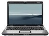
HP Dv2910us HP Pavilion dv2500 and dv2700 Notebook PC - Maintenance and Servic - Page 124
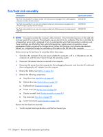
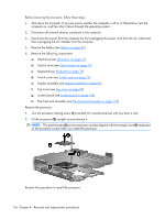
Turn the processor locking screw, one-half turn counterclockwise until you hear a click.
 |
UPC - 884420154242
View all HP Dv2910us manuals
Add to My Manuals
Save this manual to your list of manuals |
Page 124 highlights
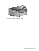
Before removing the processor, follow these steps: 1. Shut down the computer. If you are unsure whether the computer is off or in Hibernation, turn the computer on, and then shut it down through the operating system. 2. Disconnect all external devices connected to the computer. 3. Disconnect the power from the computer by first unplugging the power cord from the AC outlet and then unplugging the AC adapter from the computer. 4. Remove the battery (see Battery on page 56). 5. Remove the following components: a. Hard drive (see Hard drive on page 61) b. Optical drive (see Optical drive on page 73) c. Keyboard (see Keyboard on page 74) d. Switch cover (see Switch cover on page 79) e. Display assembly (see Display assembly on page 82) f. Top cover (see Top cover on page 87) g. System board (see System board on page 106) h. Fan/heat sink assembly (see Fan/heat sink assembly on page 112) Remove the processor: 1. Turn the processor locking screw (1) one-half turn counterclockwise until you hear a click. 2. Lift the processor (2) straight up and remove it. NOTE: The gold triangle (3) on the processor must be aligned with the triangle icon (4) embossed on the processor socket when you install the processor. Reverse this procedure to install the processor. 116 Chapter 4 Removal and replacement procedures
-
 1
1 -
2
-
3
-
4
-
5
-
6
-
7
-
8
-
9
-
10
-
11
-
12
-
13
-
14
-
15
-
16
-
17
-
18
-
19
-
20
-
21
-
22
-
23
-
24
-
25
-
26
-
27
-
28
-
29
-
30
-
31
-
32
-
33
-
34
-
35
-
36
-
37
-
38
-
39
-
40
-
41
-
42
-
43
-
44
-
45
-
46
-
47
-
48
-
49
-
50
-
51
-
52
-
53
-
54
-
55
-
56
-
57
-
58
-
59
-
60
-
61
-
62
-
63
-
64
-
65
-
66
-
67
-
68
-
69
-
70
-
71
-
72
-
73
-
74
-
75
-
76
-
77
-
78
-
79
-
80
-
81
-
82
-
83
-
84
-
85
-
86
-
87
-
88
-
89
-
90
-
91
-
92
-
93
-
94
-
95
-
96
-
97
-
98
-
99
-
100
-
101
-
102
-
103
-
104
-
105
-
106
-
107
-
108
-
109
-
110
-
111
-
112
-
113
-
114
-
115
-
116
-
117
-
118
-
 119
119 -
 120
120 -
 121
121 -
 122
122 -
 123
123 -
 124
124 -
 125
125 -
 126
126 -
 127
127 -
 128
128 -
 129
129 -
130
-
131
-
132
-
133
-
134
-
135
-
136
-
137
-
138
-
139
-
140
-
141
-
142
-
143
-
144
-
145
-
146
-
147
-
148
-
149
-
150
-
151
-
152
-
153
-
154
-
155
-
156
-
157
-
158
-
159
-
160
-
161
-
162
-
163
-
164
-
165
-
166
-
167
-
168
-
169
-
170
-
171
-
172
-
173
-
174
-
175
-
176
-
177
-
178
-
179
-
180
-
181
-
182
-
183
-
184
-
185
-
186
-
187
-
188
-
189
-
190
-
191
 |
 |
