HP Dv2910us HP Pavilion dv2500 and dv2700 Notebook PC - Maintenance and Servic - Page 66
Remove the Phillips PM2.5×4.0 screw, WWAN module; includes openings for camera module and microphones
 |
UPC - 884420154242
View all HP Dv2910us manuals
Add to My Manuals
Save this manual to your list of manuals |
Page 66 highlights
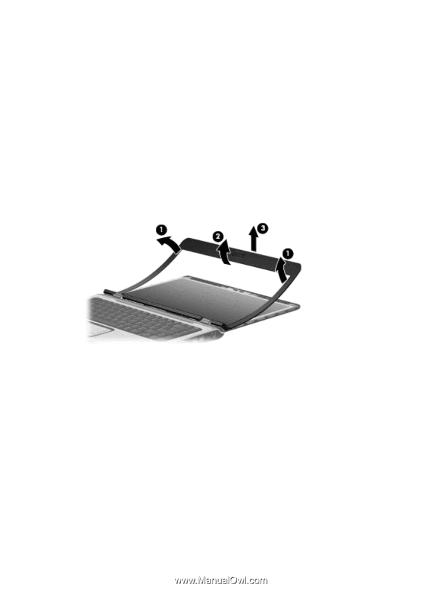
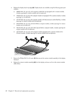
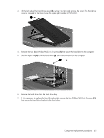
6. Release the display bezel top edge (3). Display bezels are available using the following spare part numbers: ● 448607-001 (for use only with computer models that are equipped with a camera module; includes openings for camera module and microphones) ● 448606-001 (for use only with computer models not equipped with a camera module; includes openings for microphones) ● 451907-001 (for use only with computer models with Intel processors sold at Best Buy; includes openings for camera module and microphones) ● 462529-001 (for use only with Artist Edition computer models; includes openings for camera module and microphones) ● 466185-001 (for use only with white Special Edition computer models; includes openings for camera module and microphones) ● 457796-001 (for use only with computer models equipped with a camera module and a WWAN module; includes openings for camera module and microphones) 7. Remove the Phillips PM2.5×4.0 screw (1) that secures the camera module assembly to the display enclosure. 8. Release the camera module assembly (2) from the display enclosure as far as the camera module cable allows. 58 Chapter 4 Removal and replacement procedures
-
 1
1 -
2
-
3
-
4
-
5
-
6
-
7
-
8
-
9
-
10
-
11
-
12
-
13
-
14
-
15
-
16
-
17
-
18
-
19
-
20
-
21
-
22
-
23
-
24
-
25
-
26
-
27
-
28
-
29
-
30
-
31
-
32
-
33
-
34
-
35
-
36
-
37
-
38
-
39
-
40
-
41
-
42
-
43
-
44
-
45
-
46
-
47
-
48
-
49
-
50
-
51
-
52
-
53
-
54
-
55
-
56
-
57
-
58
-
59
-
60
-
 61
61 -
 62
62 -
 63
63 -
 64
64 -
 65
65 -
 66
66 -
 67
67 -
 68
68 -
 69
69 -
 70
70 -
 71
71 -
72
-
73
-
74
-
75
-
76
-
77
-
78
-
79
-
80
-
81
-
82
-
83
-
84
-
85
-
86
-
87
-
88
-
89
-
90
-
91
-
92
-
93
-
94
-
95
-
96
-
97
-
98
-
99
-
100
-
101
-
102
-
103
-
104
-
105
-
106
-
107
-
108
-
109
-
110
-
111
-
112
-
113
-
114
-
115
-
116
-
117
-
118
-
119
-
120
-
121
-
122
-
123
-
124
-
125
-
126
-
127
-
128
-
129
-
130
-
131
-
132
-
133
-
134
-
135
-
136
-
137
-
138
-
139
-
140
-
141
-
142
-
143
-
144
-
145
-
146
-
147
-
148
-
149
-
150
-
151
-
152
-
153
-
154
-
155
-
156
-
157
-
158
-
159
-
160
-
161
-
162
-
163
-
164
-
165
-
166
-
167
-
168
-
169
-
170
-
171
-
172
-
173
-
174
-
175
-
176
-
177
-
178
-
179
-
180
-
181
-
182
-
183
-
184
-
185
-
186
-
187
-
188
-
189
-
190
-
191
 |
 |