HP Dv2910us HP Pavilion dv2500 and dv2700 Notebook PC - Maintenance and Servic - Page 118
Lift the insulation material, Remove the ExpressCard assembly
 |
UPC - 884420154242
View all HP Dv2910us manuals
Add to My Manuals
Save this manual to your list of manuals |
Page 118 highlights
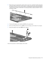
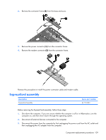
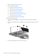
4. Remove the battery (see Battery on page 56). 5. Remove the following components: a. Hard drive (see Hard drive on page 61) b. Optical drive (see Optical drive on page 73) c. Keyboard (see Keyboard on page 74) d. Switch cover (see Switch cover on page 79) e. Display assembly (see Display assembly on page 82) f. Top cover (see Top cover on page 87) g. System board (see System board on page 106) Remove the ExpressCard assembly: 1. Lift the insulation material (1) from the system board to expose the ExpressCard assembly rear screws. 2. Remove the four Phillips PM2.0×6.0 screws (2) that secure the ExpressCard assembly to the system board. 3. Turn the system board right-side up with the front toward you. 110 Chapter 4 Removal and replacement procedures
-
 1
1 -
2
-
3
-
4
-
5
-
6
-
7
-
8
-
9
-
10
-
11
-
12
-
13
-
14
-
15
-
16
-
17
-
18
-
19
-
20
-
21
-
22
-
23
-
24
-
25
-
26
-
27
-
28
-
29
-
30
-
31
-
32
-
33
-
34
-
35
-
36
-
37
-
38
-
39
-
40
-
41
-
42
-
43
-
44
-
45
-
46
-
47
-
48
-
49
-
50
-
51
-
52
-
53
-
54
-
55
-
56
-
57
-
58
-
59
-
60
-
61
-
62
-
63
-
64
-
65
-
66
-
67
-
68
-
69
-
70
-
71
-
72
-
73
-
74
-
75
-
76
-
77
-
78
-
79
-
80
-
81
-
82
-
83
-
84
-
85
-
86
-
87
-
88
-
89
-
90
-
91
-
92
-
93
-
94
-
95
-
96
-
97
-
98
-
99
-
100
-
101
-
102
-
103
-
104
-
105
-
106
-
107
-
108
-
109
-
110
-
111
-
112
-
 113
113 -
 114
114 -
 115
115 -
 116
116 -
 117
117 -
 118
118 -
 119
119 -
 120
120 -
 121
121 -
 122
122 -
 123
123 -
124
-
125
-
126
-
127
-
128
-
129
-
130
-
131
-
132
-
133
-
134
-
135
-
136
-
137
-
138
-
139
-
140
-
141
-
142
-
143
-
144
-
145
-
146
-
147
-
148
-
149
-
150
-
151
-
152
-
153
-
154
-
155
-
156
-
157
-
158
-
159
-
160
-
161
-
162
-
163
-
164
-
165
-
166
-
167
-
168
-
169
-
170
-
171
-
172
-
173
-
174
-
175
-
176
-
177
-
178
-
179
-
180
-
181
-
182
-
183
-
184
-
185
-
186
-
187
-
188
-
189
-
190
-
191
 |
 |