HP Dv2910us HP Pavilion dv2500 and dv2700 Notebook PC - Maintenance and Servic - Page 115
Use the optical drive connector, When replacing the system board
 |
UPC - 884420154242
View all HP Dv2910us manuals
Add to My Manuals
Save this manual to your list of manuals |
Page 115 highlights
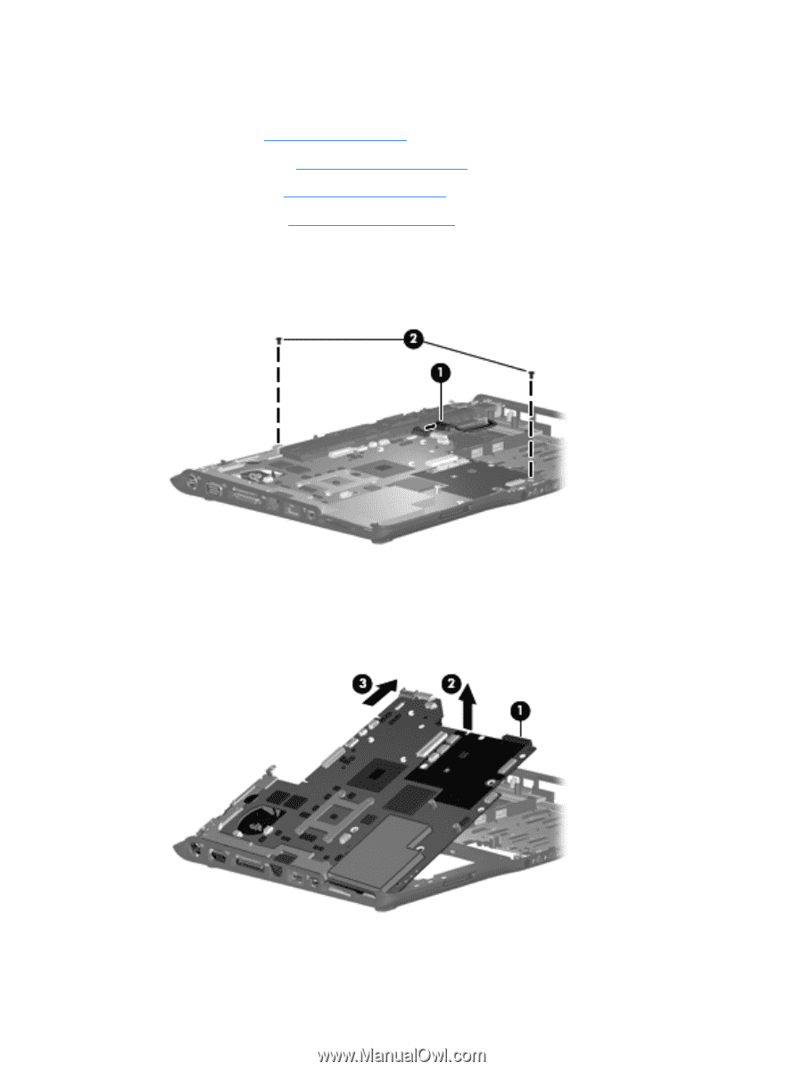
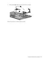
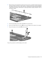
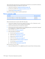
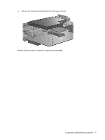
When replacing the system board, be sure that the following components are removed from the defective system board and installed on the replacement system board: ● RTC battery (see RTC battery on page 70) ● Memory modules (see Memory module on page 71) ● WLAN module (see WLAN module on page 65) ● Modem module (see Modem module on page 95) Remove the system board: 1. Disconnect the power connector cable (1) from the system board. 2. Remove the two Phillips PM2.5×5.0 screws (2) that secure the system board to the computer. 3. Use the optical drive connector (1) to lift the right side of the system board until it rests at an angle. 4. Release the system board (2) by sliding it to the right at an angle until the connectors on the left side of the system board disengage from the base enclosure. 5. Remove the system board (3). Component replacement procedures 107
-
 1
1 -
2
-
3
-
4
-
5
-
6
-
7
-
8
-
9
-
10
-
11
-
12
-
13
-
14
-
15
-
16
-
17
-
18
-
19
-
20
-
21
-
22
-
23
-
24
-
25
-
26
-
27
-
28
-
29
-
30
-
31
-
32
-
33
-
34
-
35
-
36
-
37
-
38
-
39
-
40
-
41
-
42
-
43
-
44
-
45
-
46
-
47
-
48
-
49
-
50
-
51
-
52
-
53
-
54
-
55
-
56
-
57
-
58
-
59
-
60
-
61
-
62
-
63
-
64
-
65
-
66
-
67
-
68
-
69
-
70
-
71
-
72
-
73
-
74
-
75
-
76
-
77
-
78
-
79
-
80
-
81
-
82
-
83
-
84
-
85
-
86
-
87
-
88
-
89
-
90
-
91
-
92
-
93
-
94
-
95
-
96
-
97
-
98
-
99
-
100
-
101
-
102
-
103
-
104
-
105
-
106
-
107
-
108
-
109
-
 110
110 -
 111
111 -
 112
112 -
 113
113 -
 114
114 -
 115
115 -
 116
116 -
 117
117 -
 118
118 -
 119
119 -
 120
120 -
121
-
122
-
123
-
124
-
125
-
126
-
127
-
128
-
129
-
130
-
131
-
132
-
133
-
134
-
135
-
136
-
137
-
138
-
139
-
140
-
141
-
142
-
143
-
144
-
145
-
146
-
147
-
148
-
149
-
150
-
151
-
152
-
153
-
154
-
155
-
156
-
157
-
158
-
159
-
160
-
161
-
162
-
163
-
164
-
165
-
166
-
167
-
168
-
169
-
170
-
171
-
172
-
173
-
174
-
175
-
176
-
177
-
178
-
179
-
180
-
181
-
182
-
183
-
184
-
185
-
186
-
187
-
188
-
189
-
190
-
191
 |
 |