HP Dv2910us HP Pavilion dv2500 and dv2700 Notebook PC - Maintenance and Servic - Page 90
Display assembly
 |
UPC - 884420154242
View all HP Dv2910us manuals
Add to My Manuals
Save this manual to your list of manuals |
Page 90 highlights
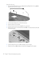
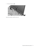
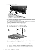
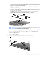
Display assembly Description Spare part number 14.1-inch, WXGA, BrightView, display assembly for use only with computer models equipped with a 448604-001 camera module (includes camera module, microphones, and WLAN transceivers and antenna cables) 14.1-inch, WXGA, BrightView, display assembly for use only with computer models not equipped with a camera module (includes microphones and WLAN transceivers and antenna cables) 448603-001 14.1-inch, WXGA, BrightView, display assembly for use only with computer models sold at Best Buy 451906-001 (includes camera module, microphones, and WLAN transceivers and antenna cables) 14.1-inch, WXGA, BrightView, display assembly for use only with computer models with Intel processors and equipped with a WWAN module (includes camera module, camera module cable, microphones, and WLAN transceivers and antenna cables) 451905-001 14.1-inch, WXGA, BrightView, display assembly for use only with Artist Edition computer models 462527-001 equipped with a camera module (includes microphones, and WLAN transceivers and antenna cables) 14.1-inch, WXGA, BrightView, display assembly for use only with white Special Edition computer 466183-001 models equipped with a camera module (includes microphones, and WLAN transceivers and antenna cables) Before removing the display assembly, follow these steps: 1. Shut down the computer. If you are unsure whether the computer is off or in Hibernation, turn the computer on, and then shut it down through the operating system. 2. Disconnect all external devices connected to the computer. 3. Disconnect the power from the computer by first unplugging the power cord from the AC outlet and then unplugging the AC adapter from the computer. 4. Remove the battery (see Battery on page 56). 5. Disconnect the wireless antenna cables from the WLAN module (see WLAN module on page 65). 6. Remove the following components: a. Keyboard (see Keyboard on page 74) b. Switch cover (see Switch cover on page 79) Remove the display assembly: 1. Close the computer and turn it upside down, with the rear panel toward you. 82 Chapter 4 Removal and replacement procedures
-
 1
1 -
2
-
3
-
4
-
5
-
6
-
7
-
8
-
9
-
10
-
11
-
12
-
13
-
14
-
15
-
16
-
17
-
18
-
19
-
20
-
21
-
22
-
23
-
24
-
25
-
26
-
27
-
28
-
29
-
30
-
31
-
32
-
33
-
34
-
35
-
36
-
37
-
38
-
39
-
40
-
41
-
42
-
43
-
44
-
45
-
46
-
47
-
48
-
49
-
50
-
51
-
52
-
53
-
54
-
55
-
56
-
57
-
58
-
59
-
60
-
61
-
62
-
63
-
64
-
65
-
66
-
67
-
68
-
69
-
70
-
71
-
72
-
73
-
74
-
75
-
76
-
77
-
78
-
79
-
80
-
81
-
82
-
83
-
84
-
 85
85 -
 86
86 -
 87
87 -
 88
88 -
 89
89 -
 90
90 -
 91
91 -
 92
92 -
 93
93 -
 94
94 -
 95
95 -
96
-
97
-
98
-
99
-
100
-
101
-
102
-
103
-
104
-
105
-
106
-
107
-
108
-
109
-
110
-
111
-
112
-
113
-
114
-
115
-
116
-
117
-
118
-
119
-
120
-
121
-
122
-
123
-
124
-
125
-
126
-
127
-
128
-
129
-
130
-
131
-
132
-
133
-
134
-
135
-
136
-
137
-
138
-
139
-
140
-
141
-
142
-
143
-
144
-
145
-
146
-
147
-
148
-
149
-
150
-
151
-
152
-
153
-
154
-
155
-
156
-
157
-
158
-
159
-
160
-
161
-
162
-
163
-
164
-
165
-
166
-
167
-
168
-
169
-
170
-
171
-
172
-
173
-
174
-
175
-
176
-
177
-
178
-
179
-
180
-
181
-
182
-
183
-
184
-
185
-
186
-
187
-
188
-
189
-
190
-
191
 |
 |