HP Dv2910us HP Pavilion dv2500 and dv2700 Notebook PC - Maintenance and Servic - Page 92
Remove the display bezel, of the display
 |
UPC - 884420154242
View all HP Dv2910us manuals
Add to My Manuals
Save this manual to your list of manuals |
Page 92 highlights
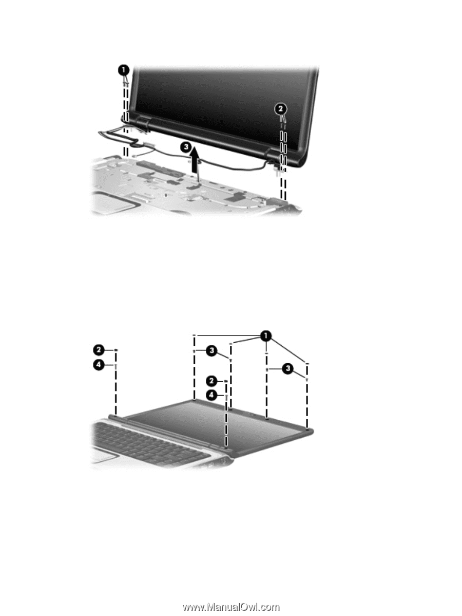
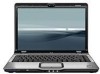
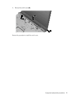
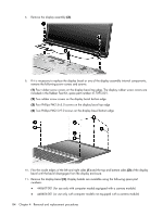
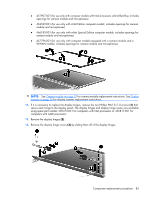
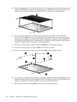
8. Remove the display assembly (3). 9. If it is necessary to replace the display bezel or any of the display assembly internal components, remove the following screw covers and screws: (1) Four rubber screw covers on the display bezel top edge. The display rubber screw covers are included in the Rubber Feet Kit, spare part number 417095-001. (2) Two rubber screw covers on the display bezel bottom edge (3) Four Phillips PM2.5×5.0 screws on the display bezel top edge (4) Two Phillips PM2.5×9.0 screws on the display bezel bottom edge 10. Flex the inside edges of the left and right sides (1) and the top and bottom sides (2) of the display bezel until the bezel disengages from the display enclosure. 11. Remove the display bezel (3). Display bezels are available using the following spare part numbers: ● 448607-001 (for use only with computer models equipped with a camera module) ● 448606-001 (or use only with computer models not equipped with a camera module) 84 Chapter 4 Removal and replacement procedures
-
 1
1 -
2
-
3
-
4
-
5
-
6
-
7
-
8
-
9
-
10
-
11
-
12
-
13
-
14
-
15
-
16
-
17
-
18
-
19
-
20
-
21
-
22
-
23
-
24
-
25
-
26
-
27
-
28
-
29
-
30
-
31
-
32
-
33
-
34
-
35
-
36
-
37
-
38
-
39
-
40
-
41
-
42
-
43
-
44
-
45
-
46
-
47
-
48
-
49
-
50
-
51
-
52
-
53
-
54
-
55
-
56
-
57
-
58
-
59
-
60
-
61
-
62
-
63
-
64
-
65
-
66
-
67
-
68
-
69
-
70
-
71
-
72
-
73
-
74
-
75
-
76
-
77
-
78
-
79
-
80
-
81
-
82
-
83
-
84
-
85
-
86
-
 87
87 -
 88
88 -
 89
89 -
 90
90 -
 91
91 -
 92
92 -
 93
93 -
 94
94 -
 95
95 -
 96
96 -
 97
97 -
98
-
99
-
100
-
101
-
102
-
103
-
104
-
105
-
106
-
107
-
108
-
109
-
110
-
111
-
112
-
113
-
114
-
115
-
116
-
117
-
118
-
119
-
120
-
121
-
122
-
123
-
124
-
125
-
126
-
127
-
128
-
129
-
130
-
131
-
132
-
133
-
134
-
135
-
136
-
137
-
138
-
139
-
140
-
141
-
142
-
143
-
144
-
145
-
146
-
147
-
148
-
149
-
150
-
151
-
152
-
153
-
154
-
155
-
156
-
157
-
158
-
159
-
160
-
161
-
162
-
163
-
164
-
165
-
166
-
167
-
168
-
169
-
170
-
171
-
172
-
173
-
174
-
175
-
176
-
177
-
178
-
179
-
180
-
181
-
182
-
183
-
184
-
185
-
186
-
187
-
188
-
189
-
190
-
191
 |
 |