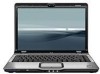
HP Dv2910us HP Pavilion dv2500 and dv2700 Notebook PC - Maintenance and Servic - Page 113
Remove the Phillips PM2.0×3.0 screw, Artist Edition models.
 |
UPC - 884420154242
View all HP Dv2910us manuals
Add to My Manuals
Save this manual to your list of manuals |
Page 113 highlights
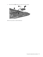
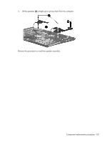
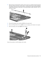
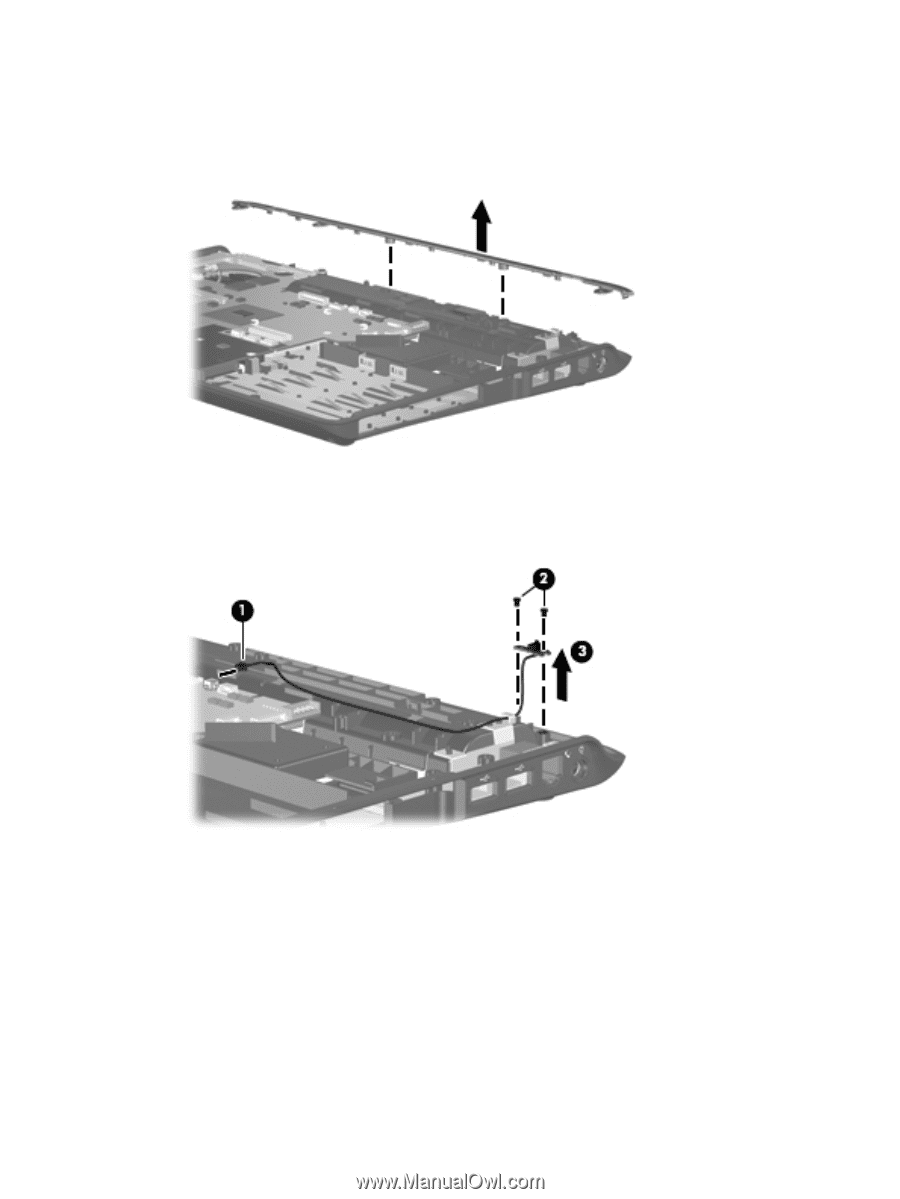
4. Remove the top cover trim from the computer. The top cover trim is included in the Door/Cover Kit, spare part number 417073-001 for basic models, as well as using spare part number 430466-001 for computers with Intel processors and a Web cam, 465309-001 for metal-colored Special Edition models with Intel processors, 465310-001 for white Special Edition models, and 465311-001 for Artist Edition models. 5. Disconnect the display switch module cable (1) from the system board. 6. Remove the Phillips PM2.0×3.0 screw (2) that secures the display switch module to the computer. 7. Remove the display switch module (3) from the computer. Reverse this procedure to install the display switch module. Component replacement procedures 105
-
 1
1 -
2
-
3
-
4
-
5
-
6
-
7
-
8
-
9
-
10
-
11
-
12
-
13
-
14
-
15
-
16
-
17
-
18
-
19
-
20
-
21
-
22
-
23
-
24
-
25
-
26
-
27
-
28
-
29
-
30
-
31
-
32
-
33
-
34
-
35
-
36
-
37
-
38
-
39
-
40
-
41
-
42
-
43
-
44
-
45
-
46
-
47
-
48
-
49
-
50
-
51
-
52
-
53
-
54
-
55
-
56
-
57
-
58
-
59
-
60
-
61
-
62
-
63
-
64
-
65
-
66
-
67
-
68
-
69
-
70
-
71
-
72
-
73
-
74
-
75
-
76
-
77
-
78
-
79
-
80
-
81
-
82
-
83
-
84
-
85
-
86
-
87
-
88
-
89
-
90
-
91
-
92
-
93
-
94
-
95
-
96
-
97
-
98
-
99
-
100
-
101
-
102
-
103
-
104
-
105
-
106
-
107
-
 108
108 -
 109
109 -
 110
110 -
 111
111 -
 112
112 -
 113
113 -
 114
114 -
 115
115 -
 116
116 -
 117
117 -
 118
118 -
119
-
120
-
121
-
122
-
123
-
124
-
125
-
126
-
127
-
128
-
129
-
130
-
131
-
132
-
133
-
134
-
135
-
136
-
137
-
138
-
139
-
140
-
141
-
142
-
143
-
144
-
145
-
146
-
147
-
148
-
149
-
150
-
151
-
152
-
153
-
154
-
155
-
156
-
157
-
158
-
159
-
160
-
161
-
162
-
163
-
164
-
165
-
166
-
167
-
168
-
169
-
170
-
171
-
172
-
173
-
174
-
175
-
176
-
177
-
178
-
179
-
180
-
181
-
182
-
183
-
184
-
185
-
186
-
187
-
188
-
189
-
190
-
191
 |
 |
4
.
Remove the top cover trim from the computer. The top cover trim is included in the Door/Cover Kit,
spare part number 417073-001 for basic models, as well as using spare part number 430466-001
for computers with Intel processors and a Web cam, 465309-001 for metal-colored Special Edition
models with Intel processors, 465310-001 for white Special Edition models, and 465311-001 for
Artist Edition models.
5
.
Disconnect the display switch module cable
(1)
from the system board.
6
.
Remove the Phillips PM2.0×3.0 screw
(2)
that secures the display switch module to the computer.
7
.
Remove the display switch module
(3)
from the computer.
Reverse this procedure to install the display switch module.
Component replacement procedures
105