HP Dv2910us HP Pavilion dv2500 and dv2700 Notebook PC - Maintenance and Servic - Page 88
Lift the front edge of the switch cover, is connected and disconnect the cable
 |
UPC - 884420154242
View all HP Dv2910us manuals
Add to My Manuals
Save this manual to your list of manuals |
Page 88 highlights
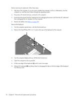
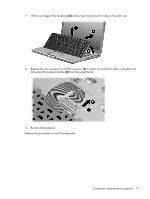
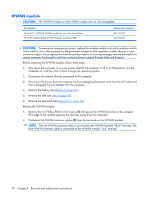
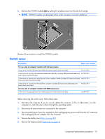
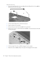
Remove the switch cover: 1. Remove the three Phillips PM2.5×9.0 screws (1) and the silver Phillips PM2.5×5.0 screw (2) that secure the switch cover to the computer. 2. Turn the computer display-side up, with the front toward you. 3. Open the computer as far as possible. 4. Disconnect the power button board cable (1) from the system board. 5. Release the ZIF connector to which the LED board cable (2) is connected and disconnect the cable from the system board. 6. Lift the front edge of the switch cover (1) to disengage it from the computer. 7. Release the switch cover (2) by sliding it to the right until it disengages from the computer. 80 Chapter 4 Removal and replacement procedures
-
 1
1 -
2
-
3
-
4
-
5
-
6
-
7
-
8
-
9
-
10
-
11
-
12
-
13
-
14
-
15
-
16
-
17
-
18
-
19
-
20
-
21
-
22
-
23
-
24
-
25
-
26
-
27
-
28
-
29
-
30
-
31
-
32
-
33
-
34
-
35
-
36
-
37
-
38
-
39
-
40
-
41
-
42
-
43
-
44
-
45
-
46
-
47
-
48
-
49
-
50
-
51
-
52
-
53
-
54
-
55
-
56
-
57
-
58
-
59
-
60
-
61
-
62
-
63
-
64
-
65
-
66
-
67
-
68
-
69
-
70
-
71
-
72
-
73
-
74
-
75
-
76
-
77
-
78
-
79
-
80
-
81
-
82
-
 83
83 -
 84
84 -
 85
85 -
 86
86 -
 87
87 -
 88
88 -
 89
89 -
 90
90 -
 91
91 -
 92
92 -
 93
93 -
94
-
95
-
96
-
97
-
98
-
99
-
100
-
101
-
102
-
103
-
104
-
105
-
106
-
107
-
108
-
109
-
110
-
111
-
112
-
113
-
114
-
115
-
116
-
117
-
118
-
119
-
120
-
121
-
122
-
123
-
124
-
125
-
126
-
127
-
128
-
129
-
130
-
131
-
132
-
133
-
134
-
135
-
136
-
137
-
138
-
139
-
140
-
141
-
142
-
143
-
144
-
145
-
146
-
147
-
148
-
149
-
150
-
151
-
152
-
153
-
154
-
155
-
156
-
157
-
158
-
159
-
160
-
161
-
162
-
163
-
164
-
165
-
166
-
167
-
168
-
169
-
170
-
171
-
172
-
173
-
174
-
175
-
176
-
177
-
178
-
179
-
180
-
181
-
182
-
183
-
184
-
185
-
186
-
187
-
188
-
189
-
190
-
191
 |
 |
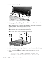
Remove the switch cover:
1
.
Remove the three Phillips PM2.5×9.0 screws
(1)
and the silver Phillips PM2.5×5.0 screw
(2)
that
secure the switch cover to the computer.
2
.
Turn the computer display-side up, with the front toward you.
3
.
Open the computer as far as possible.
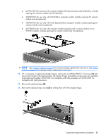
4
.
Disconnect the power button board cable
(1)
from the system board.
5
.
Release the ZIF connector to which the LED board cable
(2)
is connected and disconnect the cable
from the system board.
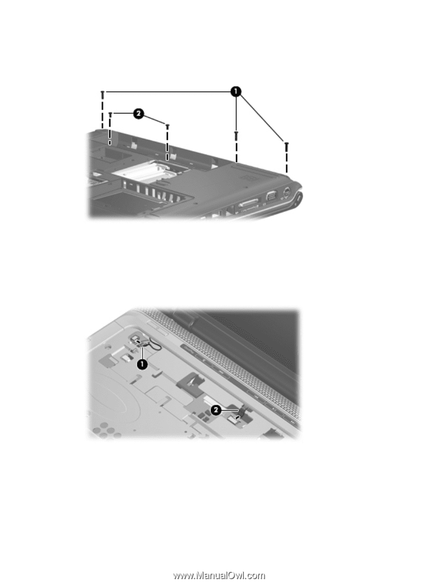
6
.
Lift the front edge of the switch cover
(1)
to disengage it from the computer.
7
.
Release the switch cover
(2)
by sliding it to the right until it disengages from the computer.
80
Chapter
4
Removal and replacement procedures