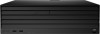
HP Engage Flex Pro G2 Maintenance and Service Guide
HP Engage Flex Pro G2 Manual
 |
View all HP Engage Flex Pro G2 manuals
Add to My Manuals
Save this manual to your list of manuals |
HP Engage Flex Pro G2 manual content summary:
- HP Engage Flex Pro G2 | Maintenance and Service Guide - Page 1
Maintenance and Service Guide SUMMARY This guide provides maintenance information about such topics as spare parts, removal and replacement of parts, security, and backing up. - HP Engage Flex Pro G2 | Maintenance and Service Guide - Page 2
HP products and services are set forth in the express warranty statements accompanying such products and services. Nothing herein should access the latest user guides, go to http://www.hp.com/support, and follow the instructions to find your product. Then select Manuals. Software terms By - HP Engage Flex Pro G2 | Maintenance and Service Guide - Page 3
Safety warning notice Reduce the possibility of heat-related injuries or of overheating the computer by following the practices described. WARNING! To reduce the possibility of heat-related injuries or of overheating the computer, do not place the computer directly on your lap or obstruct the - HP Engage Flex Pro G2 | Maintenance and Service Guide - Page 4
cleaning safety precautions ...15 Cleaning the computer case...16 Cleaning the keyboard...16 Cleaning the monitor ...17 Cleaning the mouse...17 Service considerations...17 Tools and software requirements...17 Screws ...17 Cables and connectors...17 Hard drives ...18 Lithium coin cell battery...18 - HP Engage Flex Pro G2 | Maintenance and Service Guide - Page 5
Battery...22 Optical drive...23 Front bezel...23 Extra screw locations...25 Rotating the drive cage ...26 Memory modules (DIMMs)...27 Expansion cards ...30 Expansion cards...31 Riser assembly...33 Solid-state drive...38 Front I/O assembly...40 Speaker...42 Optical drive cage ...43 Rotating the power - HP Engage Flex Pro G2 | Maintenance and Service Guide - Page 6
Windows...94 Accessing HP PC Hardware Diagnostics Windows from HP Support Assistant 94 Accessing HP PC Hardware Diagnostics Windows from the UEFI ...96 Starting HP PC Hardware Diagnostics UEFI through HP Hotkey Support software (select products only)...97 Downloading HP PC Hardware Diagnostics UEFI - HP Engage Flex Pro G2 | Maintenance and Service Guide - Page 7
Japanese power cord requirements...105 Country-specific requirements ...105 12 Specifications ...107 Index...108 vii - HP Engage Flex Pro G2 | Maintenance and Service Guide - Page 8
assistance and to learn more about the hardware and software installed on your computer model, run the HP Support Assistant utility. NOTE: You can use this computer model in a tower orientation or a desktop orientation. See Changing from desktop to tower orientation on page 5. HP - HP Engage Flex Pro G2 | Maintenance and Service Guide - Page 9
light on the power button is normally white when the power is on. If the light blinks red, the computer displays a diagnostic code to indicate a problem. Rear panel components To identify the rear panel components, use this illustration and table. 2 Chapter 1 Computer features - HP Engage Flex Pro G2 | Maintenance and Service Guide - Page 10
Table 1-2 Identifying the rear panel components Rear panel components 1 PCIe® x16 expansion slot (optional) 10 2 PCIe x4 expansion slot (optional)* 11 3 Audio-out (headphone)/Audio-in (microphone) 12 combo jack 4 PCIe x1 expansion slot (optional) 13 5 14 PCIe x1 expansion slot ( - HP Engage Flex Pro G2 | Maintenance and Service Guide - Page 11
ports. The recommended distance is 40 cm from the computer. NOTE: The combo jack supports headphones, line output devices, microphones, line input devices, or CTIA-style headsets. computer. Keep these numbers available when contacting customer service for assistance. 4 Chapter 1 Computer features - HP Engage Flex Pro G2 | Maintenance and Service Guide - Page 12
Changing from desktop to tower orientation You can use the computer in a tower orientation with an optional tower stand that you can purchase from HP. NOTE: To stabilize the computer in a tower orientation, HP recommends the use of the optional tower stand. 1. Remove or disengage any security - HP Engage Flex Pro G2 | Maintenance and Service Guide - Page 13
6. Reconnect the power cord and any external devices, and then turn on the computer. NOTE: Be sure that at least 10.2 centimeters (4 inches) of space on all sides of the computer remains clear and free of obstructions. 7. Lock any security devices that you disengaged before you moved the computer. - HP Engage Flex Pro G2 | Maintenance and Service Guide - Page 14
and changes product parts. For complete and current information about supported parts for your computer, go to https://partsurfer.hp.com/partsurfer/, select your country or region, and then follow the on-screen instructions. Computer major components To identify the computer major components, use - HP Engage Flex Pro G2 | Maintenance and Service Guide - Page 15
Table 2-1 Computer major components and their descriptions (continued) Item Description (6) Heat sink (7) Processor Intel® Core® i5-13500TE processor Intel Core i5-13500E processor Intel Core i3-13100TE processor Intel Core i3-13100E processor (8) System board NOTE: System boards are - HP Engage Flex Pro G2 | Maintenance and Service Guide - Page 16
Table 2-1 Computer major components and their descriptions (continued) Item Description Power serial adapter Dual-powered USB-to-serial port Cash drawer 24 V powered port (15) Hood sensor (16) Graphics card NVIDIA® T1000 NVIDIA RTX® A2000 (17) Fan duct (18) Fan (19) Hard drive (3.5 - HP Engage Flex Pro G2 | Maintenance and Service Guide - Page 17
Table 2-2 Miscellaneous parts and their descriptions Description Cables SATA cable, 28.0 cm (11.0 in), two straight ends SATA cable, 28.0 cm (11.0 in), two straight ends, RF SATA cable, 49.5 cm (19.5 in), two straight ends SATA cable, 49.5 cm (19.5 in), two straight ends, RF SATA cable, 64.0 cm (25 - HP Engage Flex Pro G2 | Maintenance and Service Guide - Page 18
Table 2-2 Miscellaneous parts and their descriptions (continued) Description Optical drive adapter Optical drive bezel Computer chassis rear bracket Plastic WLAN antenna cover Low profile bracket for P600/P1000 graphics cards External wireless antenna Access panel plastic latch Power cord (C13, 1.83 - HP Engage Flex Pro G2 | Maintenance and Service Guide - Page 19
information for the computer. Adherence to the procedures and precautions is essential for proper service. IMPORTANT: When the computer is plugged into an AC power source, DC voltage is always applied to the system board. You must disconnect the power - HP Engage Flex Pro G2 | Maintenance and Service Guide - Page 20
Table 3-1 Static electricity occurrence based on activity and humidity (continued) Relative humidity Walking across carpet 7,500 V 15,000 V Walking across vinyl floor 3,000 V 5,000 V Motions of bench worker 400 V 800 V Removing DIPs (dual in-line packages) from plastic tube 400 V 700 V - HP Engage Flex Pro G2 | Maintenance and Service Guide - Page 21
workstations with ground cord of 1 MΩ ±10% resistance ● Static-dissipative table or floor mats with hard tie to ground ● Field service kits ● Static awareness labels ● Wrist straps and footwear straps providing 1 MΩ ±10% resistance ● Material handling packages ● Conductive plastic bags ● Conductive - HP Engage Flex Pro G2 | Maintenance and Service Guide - Page 22
● Opaque shielding bags ● Transparent metallized shielding bags ● Transparent shielding tubes Operating guidelines This information details how to prevent overheating and to help prolong the life of the computer. ● Keep the computer away from excessive moisture, direct sunlight, and extremes of heat - HP Engage Flex Pro G2 | Maintenance and Service Guide - Page 23
● Disconnect the keyboard before cleaning it. ● Wear safety glasses equipped with side shields when cleaning the keyboard. Cleaning the computer case Follow all safety precautions before cleaning the computer case. To clean the computer case, follow these procedures: NOTE: You can also use these - HP Engage Flex Pro G2 | Maintenance and Service Guide - Page 24
considerations Keep these considerations in mind during the disassembly and assembly of the computer. Tools and software requirements Servicing the computer requires these tools. ● Torx T-15 screwdriver ● Flat-bladed screwdriver (can sometimes be used in place of the Torx screwdriver) ● Phillips - HP Engage Flex Pro G2 | Maintenance and Service Guide - Page 25
or snagged by parts being removed or replaced. IMPORTANT: When servicing this computer, be sure to place cables in their proper location approximately three years. See the removal and replacement chapter for replacement instructions. WARNING! This computer contains a lithium battery. There is a - HP Engage Flex Pro G2 | Maintenance and Service Guide - Page 26
Table 3-3 SATA hard drive characteristics Serial ATA hard drive characteristics Number of pins/conductors in data cable Number of pins in power cable Maximum data cable length Data interface voltage differential Drive voltages Jumpers for configuring drive Data transfer rate 7/7 15 100 cm (39.37 in - HP Engage Flex Pro G2 | Maintenance and Service Guide - Page 27
guide are available on all computers. NOTE: HP continually improves and changes product parts. For complete and current information about supported parts for your computer, go to https://partsurfer.hp.com/partsurfer/, select your country or region, and then follow the on-screen instructions servicing - HP Engage Flex Pro G2 | Maintenance and Service Guide - Page 28
■ Pull the dust filter straight off the outside of the front bezel. To install the dust filter, reverse the removal procedure. Access panel To remove the access panel, use this procedure and illustration. Before removing the access panel, prepare the computer for disassembly (see Preparation for - HP Engage Flex Pro G2 | Maintenance and Service Guide - Page 29
Battery To remove the battery, use these procedures. The battery that comes with the computer provides power to the real-time clock. When replacing the battery, use a battery equivalent to the battery originally installed in the computer. The computer comes with a 3 V lithium coin cell battery. - HP Engage Flex Pro G2 | Maintenance and Service Guide - Page 30
2. Slide the replacement battery into position, positive side up. The battery holder automatically secures the battery in the proper position. Optical drive To remove the optical drive, use this procedure and illustration. Before removing the optical drive, follow these steps: 1. Prepare the - HP Engage Flex Pro G2 | Maintenance and Service Guide - Page 31
1. If the bezel is locked with a security screw, remove the screw from the top of the bezel. 2. If a USB cap is installed, use a flat pry tool to release the cap from the bezel. 3. Lift the three tabs (1) at the top of the bezel. 24 Chapter 4 Removal and replacement procedures - HP Engage Flex Pro G2 | Maintenance and Service Guide - Page 32
4. Rotate the top of the bezel outward (2), and then pull the bezel (3) away from the computer. 5. To remove the blank from the bezel, press the release tabs (1) on the inside of the bezel, and then rotate the blank (2) off the outside of the bezel. To install the front bezel, reverse the removal - HP Engage Flex Pro G2 | Maintenance and Service Guide - Page 33
Table 4-1 Extra screw locations Item Expansion slot (1) Four silver 6/32 inch component screws (2) One silver security screw (3) Four black M3 drive screws Rotating the drive cage To rotate the drive cage upright, use this procedure and illustration. Before rotating the drive cage, follow - HP Engage Flex Pro G2 | Maintenance and Service Guide - Page 34
DIMMs ● 32 GB PC5-4800E, dual ranked, 4800 Mbps DDR5, unbuffered, ECC DIMMs ● Single and dual rank, 16 GB based DIMMs ● System ECC is supported on unbuffered ECC DIMMs NOTE: The system might not operate properly if you install unsupported memory modules. There are four memory sockets on the system - HP Engage Flex Pro G2 | Maintenance and Service Guide - Page 35
are automatically corrected. ● Detected multi-bit errors cause the system to immediately reboot and halt with an F1 prompt error message. NOTE: Although HP does support non-ECC memory on this platform, non-ECC memory does not fully detect or correct single-bit or multi-bit errors, which can cause - HP Engage Flex Pro G2 | Maintenance and Service Guide - Page 36
Static electricity can damage the electronic components of the computer or optional cards. Before beginning these procedures, be sure that you are discharged of static electricity by briefly touching a grounded metal object. For more information, see Electrostatic discharge information on page 12. - HP Engage Flex Pro G2 | Maintenance and Service Guide - Page 37
2. To install a memory module, open both latches (1) of the memory module socket, and insert the memory module into the socket (2). Press the module down into the socket so that the module is fully inserted and properly seated. Be sure that the latches (3) are in the closed position. NOTE: A memory - HP Engage Flex Pro G2 | Maintenance and Service Guide - Page 38
Table 4-3 Expansion slot locations Item Expansion slot (1) PCI Express ×16 (2) PCI Express ×4 (3) PCI Express ×2 (4) Riser card slot (5) PCI Express ×2 IMPORTANT: The riser card expansion slot is specifically designed for the riser card for this product only. Do not attempt to plug any - HP Engage Flex Pro G2 | Maintenance and Service Guide - Page 39
1. Release the slot cover retention latch that secures the slot covers by lifting the green tab on the latch and rotating the latch to the open position. NOTE: Before removing an installed expansion card, disconnect any cables that may be attached to the expansion card. 2. To remove a PCIe card, - HP Engage Flex Pro G2 | Maintenance and Service Guide - Page 40
3. To remove a PCI card, pull the expansion card straight up and then away from the inside of the chassis to release it from the chassis frame. Be sure not to scrape the card against other components. CAUTION: After removing an expansion card, you must replace it with a new card or expansion slot - HP Engage Flex Pro G2 | Maintenance and Service Guide - Page 41
b. Pull the expansion card out of the socket on the riser assembly. c. Different expansion cards might require a different bracket. The following illustration provides an example of removing a bracket from an expansion card by removing two screws (1) and pulling the bracket (2) off the card. 2. To - HP Engage Flex Pro G2 | Maintenance and Service Guide - Page 42
a. Release the slot cover retention latch that by lifting the green tab on the latch and rotating the latch to the open position. b. Lift the riser assembly out of the riser card slot. Riser assembly 35 - HP Engage Flex Pro G2 | Maintenance and Service Guide - Page 43
c. To disassemble the riser assembly, remove two screws that secure the bracket to the assembly, and then remove the bracket. 3. To install an expansion card into the riser assembly: a. Pull back the tab on the expansion card retention latch to open the latch. 36 Chapter 4 Removal and replacement - HP Engage Flex Pro G2 | Maintenance and Service Guide - Page 44
b. If installed, rotate an expansion slot cover to remove it from the riser assembly. c. Insert the end of the expansion card into an empty slot (1), and then press the other end against the chassis (2). NOTE: A powered serial port is shown. The expansion card can vary. d. If necessary, connect one - HP Engage Flex Pro G2 | Maintenance and Service Guide - Page 45
Solid-state drive To remove the solid-state drive, use these procedures and illustrations. For a list of available solid-states drives, see Computer major components on page 7. Before removing the solid-state drive, follow these steps: 1. Prepare the computer for disassembly (see Preparation for - HP Engage Flex Pro G2 | Maintenance and Service Guide - Page 46
2. Remove the Phillips screw (1) that secures the drive. 3. Rotate the drive upward (2), and then pull the drive out of the socket (3). 4. To remove the heat sink from the drive, pull all four heat sink arms (1) down slightly, and then pull the arms out of the slots (2) in the bracket. 5. Lift the - HP Engage Flex Pro G2 | Maintenance and Service Guide - Page 47
6. When installing a solid-state drive, be sure thermal pads are installed on the bottom of the heat sink (1) and the inside of the bracket (2). To install the solid-state drive, reverse the removal procedure. Front I/O assembly To remove the front I/O assembly, use these procedures and - HP Engage Flex Pro G2 | Maintenance and Service Guide - Page 48
1. Remove one Torx screw (1) from the front grill, and then rotate the grill (2) from right to left and off the front of the computer. 2. Disconnect the cable from the PB/LED connector (1) on system board. 3. Disconnect the cable from the FRONT USB3 connector (2) on system board. 4. From the front - HP Engage Flex Pro G2 | Maintenance and Service Guide - Page 49
8. Pull the assembly and cables (4) out of the front of the computer. To install the front I/O assembly, reverse the removal procedure. Speaker To remove the speaker, use this procedure and illustration. Before removing the speaker, follow these steps: 1. Prepare the computer for disassembly (see - HP Engage Flex Pro G2 | Maintenance and Service Guide - Page 50
3. Remove the speaker from the connectors (3). To install the speaker, reverse the removal procedure. Optical drive cage To remove the optical drive cage, use this procedure and illustration. Before removing the optical drive cage, follow these steps: 1. Prepare the computer for disassembly (see - HP Engage Flex Pro G2 | Maintenance and Service Guide - Page 51
2. Slide the cage (2) toward the back of the computer, and then lift the cage (3) up and out of the computer. To replace the optical drive cage, reverse this procedure. Rotating the power supply To rotate the power supply upright, use this procedure and illustration. Before rotating the power supply - HP Engage Flex Pro G2 | Maintenance and Service Guide - Page 52
WLAN module To remove the WLAN module, use these procedures. Before removing the WLAN module, follow these steps: 1. Prepare the computer for disassembly (see Preparation for disassembly on page 20). 2. Remove the access panel (see Access panel on page 21). 3. Rotate the power supply to the upright - HP Engage Flex Pro G2 | Maintenance and Service Guide - Page 53
5. If the WLAN antenna is not connected to the terminal on the WLAN module, a protective sleeve must be installed on the antenna connector, as shown in the following illustration. To install the WLAN module, reverse the removal procedure. NOTE: WLAN modules are designed with a notch to prevent - HP Engage Flex Pro G2 | Maintenance and Service Guide - Page 54
Remove the secondary hard drive from the drive cage: 1. Remove the optical drive cage from the rotating drive cage (see Optical drive cage on page 43). 2. Disconnect the power and data cables (1) from the back of the drive. 3. Press the release button (2), and then slide the drive (3) out of the - HP Engage Flex Pro G2 | Maintenance and Service Guide - Page 55
1. Prepare the computer for disassembly (see Preparation for disassembly on page 20). 2. Remove the access panel (see Access panel on page 21). Remove the fan duct: 1. Remove the cable from the clip (1) on the duct. 2. Lift the duct (2) straight up and out of the computer. To install the fan duct, - HP Engage Flex Pro G2 | Maintenance and Service Guide - Page 56
3. Remove the fan (3) from the computer. To install the fan, reverse the removal procedure. Heat sink To remove the heat sink, use this procedure and illustration. Before removing the heat sink, follow these steps: 1. Prepare the computer for disassembly (see Preparation for disassembly on page 20). - HP Engage Flex Pro G2 | Maintenance and Service Guide - Page 57
3. Thoroughly clean and replace the thermal grease from the surfaces on the system board and heat sink each time the heat sink is removed. Be sure that thermal grease is installed on the heat sink as shown in the following illustration. To install the heat sink, reverse the removal procedures. - HP Engage Flex Pro G2 | Maintenance and Service Guide - Page 58
To install the processor, reverse the removal procedures. NOTE: After installing a new processor onto the system board, update the system ROM to ensure that the computer using the latest version of the BIOS. Flex card To remove the flex card, use this procedure and illustration. Before removing the - HP Engage Flex Pro G2 | Maintenance and Service Guide - Page 59
3. Remove the flex card and cable (3) from the computer. To install the flex card, reverse the removal procedure. Audio board To remove the audio board, use this procedure and illustration. Before removing the audio board, follow these steps: 1. Prepare the computer for disassembly (see Preparation - HP Engage Flex Pro G2 | Maintenance and Service Guide - Page 60
To install the audio board, reverse the removal procedure. Serial port To remove the serial port, use this procedure and illustration. Before removing the serial port, follow these steps: 1. Prepare the computer for disassembly (see Preparation for disassembly on page 20). 2. Remove the access panel - HP Engage Flex Pro G2 | Maintenance and Service Guide - Page 61
1. Remove the two Phillips screws (1) from the port. 2. Lift the port (2) up to disconnect it from the connector on the system board. To install the rear expansion port, reverse this procedure. WLAN antennas and external connectors To remove the WLAN antennas and external connectors, use this - HP Engage Flex Pro G2 | Maintenance and Service Guide - Page 62
5. Remove the connector assembly and cables (5) from the computer. To install the WLAN antennas and external connectors, reverse the removal procedure. Power supply To remove the power supply, use these procedures. Before removing the power supply, follow these steps: 1. Prepare the computer for - HP Engage Flex Pro G2 | Maintenance and Service Guide - Page 63
2. Rotate the power supply (1) up approximately 90°. 3. Slide the power supply forward (2), and then lift it up and out of the computer (3). To install the power supply, reverse the removal procedures. System board To remove the system board, use this procedure and illustration. NOTE: All system - HP Engage Flex Pro G2 | Maintenance and Service Guide - Page 64
5. Rotate the drive cage to the upright position (see Rotating the drive cage on page 26). 6. Rotate the power supply to the upright position (see Rotating the power supply on page 44). 7. Remove the fan baffle (see Fan duct on page 47). When you replace the system board, be sure to remove the - HP Engage Flex Pro G2 | Maintenance and Service Guide - Page 65
2. Remove the eight Torx screws (1) from the board. 3. Slide the system board (2) toward the front of the computer enough to remove the connectors from the back of computer, and then lift the system board (3) out of the computer. To install the system board, reverse the removal procedure. NOTE: When - HP Engage Flex Pro G2 | Maintenance and Service Guide - Page 66
they are unsecured. ● Enable or disable different types of boot sources. ● Configure features such as Secure Boot, power management, virtualization support, and language and keyboard type used in Setup and POST. ● Replicate the system setup by saving system configuration information about a USB - HP Engage Flex Pro G2 | Maintenance and Service Guide - Page 67
turn off the computer only after exiting the F10 Setup screen. Computer Setup Main This table provides information about the Computer Setup Main menu. NOTE: Support for specific Computer Setup options can vary, depending on the hardware configuration. 60 Chapter 5 Computer Setup (F10) Utility - HP Engage Flex Pro G2 | Maintenance and Service Guide - Page 68
Table 5-1 Computer Setup Main Option Description System Information Lists all information in following list if Advanced System Information is selected. Lists smaller subset if Basic System Information is selected. ● Product name ● Installed memory size ● Processor type ● Processor cache size - HP Engage Flex Pro G2 | Maintenance and Service Guide - Page 69
Table 5-1 Computer Setup Main (continued) Option Description System Diagnostics If the hard drive has the HP Advanced Diagnostics installed, the application launches. If HP Advanced Diagnostics is not installed, a basic version that is built into the BIOS provides the capability to perform the - HP Engage Flex Pro G2 | Maintenance and Service Guide - Page 70
BIOS version, and updates are not allowed. Native OS Firmware Update Service Allows the operating system to drive firmware updates (for example, Windows BIOS: If selected, Minimum BIOS Version becomes active, which lets you manually enter the minimum BIOS version that you can roll back to. - HP Engage Flex Pro G2 | Maintenance and Service Guide - Page 71
system configuration, exits Computer Setup, and reboots. Computer Setup Security This table provides information about the Computer Setup Security menu. NOTE: Support for specific Computer Setup options can vary, depending on the hardware configuration. 64 Chapter 5 Computer Setup (F10) Utility - HP Engage Flex Pro G2 | Maintenance and Service Guide - Page 72
Table 5-2 Computer Setup Security Option Description Create BIOS Lets you set and enable a BIOS administrator password, which controls access to the following Administrator Password features: ● Setup Menu (F10) ● Third-Party Option ROM Management (F3) ● Update system ROM ● WMI commands that - HP Engage Flex Pro G2 | Maintenance and Service Guide - Page 73
Block on every boot: Select to enable HP Sure Start. Default is disabled. ● BIOS Data Recovery Policy: Select Automatic or Manual to determine data recovery process. Manual recovery is intended only for situations when you want forensic analysis before HP Sure Start recovery. When this policy is - HP Engage Flex Pro G2 | Maintenance and Service Guide - Page 74
CA key: Disabling this setting alters the Secure Boot key list to further restrict the allowed software components. Set this option to disable to support Device Guard. Default is enabled. - Ready BIOS for Device Guard Use: Requires BIOS Administrator password to be configured and Secure Boot to be - HP Engage Flex Pro G2 | Maintenance and Service Guide - Page 75
power up when changes are made to system security policy. The user must manually agree to those changes before the change is confirmed. Default is enabled. Guard Extensions (SGX) Intel SGX is a set of processor code instructions that allows user-level code to allocate private regions of memory. - HP Engage Flex Pro G2 | Maintenance and Service Guide - Page 76
of System Hard Drive Enabling this feature saves the GUID Partition Table (GPT) of the system hard drive selection appears only when at least one drive that supports the DriveLock feature is attached to the system. reset security settings during a service event. Default is enabled. Restore - HP Engage Flex Pro G2 | Maintenance and Service Guide - Page 77
Computer Setup Advanced This table provides information about the Computer Setup Advanced menu. NOTE: Support for specific Computer Setup options can vary, depending on the hardware configuration. Table 5-3 Computer Setup Advanced (for advanced users) Option Heading Display Language Lets you - HP Engage Flex Pro G2 | Maintenance and Service Guide - Page 78
Table 5-3 Computer Setup Advanced (for advanced users) (continued) Option Heading Boot Options NOTE: Use the UP and DOWN arrows to highlight an item. Press enter to select. Use the UP and DOWN arrows to move a selected item. Press f5 to enable or disable. Press esc to exit. NOTE: MS-DOS drive - HP Engage Flex Pro G2 | Maintenance and Service Guide - Page 79
(AMD® products only) Enables AMD-V and AMD-Vi virtualization features on AMD-based systems Enhanced Hello Sign-in (systems with supporting hardware for biometric identification only) Allows for secure logon using the Windows Hello feature. DMA Protection Enables DMA redirection using IOMMU for - HP Engage Flex Pro G2 | Maintenance and Service Guide - Page 80
(ACPI table). HP Application Driver Provides ACPI structure to enable HP common software application framework. The driver is provided in the latest HP support software that you can download from the web. NOTE: Device Manager shows an alert if this setting is enabled without the HP application - HP Engage Flex Pro G2 | Maintenance and Service Guide - Page 81
Table 5-3 Computer Setup Advanced (for advanced users) (continued) Option Heading Built-In Device Options Embedded LAN Controller (select products only) Select to show the device in the operating system. Default is enabled. Wake On LAN Lets you either disable the Wake On LAN feature or - HP Engage Flex Pro G2 | Maintenance and Service Guide - Page 82
Table 5-3 Computer Setup Advanced (for advanced users) (continued) Option Heading Built-In Device Options Collaboration Buttons (select products only) Clear to disable the collaboration buttons. Default is enabled. Button Sensitivity (select products only) Controls touch sensitivity of - HP Engage Flex Pro G2 | Maintenance and Service Guide - Page 83
Table 5-3 Computer Setup Advanced (for advanced users) (continued) Option Heading Port Options USB ports (varies by model) Lets you enable specific USB ports. Default is enabled. USB Legacy Port Charging Lets you enable USB charging port capability when the computer is in hibernate or - HP Engage Flex Pro G2 | Maintenance and Service Guide - Page 84
Table 5-3 Computer Setup Advanced (for advanced users) (continued) Option Heading Power Management Options Runtime Power Management Allows certain operating systems to reduce processor voltage and frequency when the current software load does not require the full capabilities of the processor. - HP Engage Flex Pro G2 | Maintenance and Service Guide - Page 85
Provisioning Support Enables AMT provisioning using a USB storage device. Default is disabled. USB Redirection Support USB min. CIRA Timeout (min.) CIRA is Customer Initiated Remote Assistance, an Intel service to help users employing Active Management Technology (AMT). Default is 1. 78 Chapter - HP Engage Flex Pro G2 | Maintenance and Service Guide - Page 86
-express interface, thus any Thunderbolt device that requires PCI-Express will not function correctly. Native PCIe Hot Plug Enables hot plug support to the system PCI-Express bus. Remote HP PC Hardware Diagnostics Settings Sets the configuration for Remote HP PC Hardware Diagnostics, including - HP Engage Flex Pro G2 | Maintenance and Service Guide - Page 87
-Test (POST) or computer restart, the probable source of the problem, and steps you can take to resolve the error condition. POST messages. If a POST error occurs, the screen will display the error message. To manually switch to the POST Messages Enabled mode during POST, press any key except f10, - HP Engage Flex Pro G2 | Maintenance and Service Guide - Page 88
Control Panel (Computer Setup can also be used). If the problem persists, replace the RTC battery. See Removal and replacement procedures on page 20 for instructions about installing a new battery. 008-Microcode Patch Error Processor is not supported by the BIOS. 1. Upgrade BIOS to proper version - HP Engage Flex Pro G2 | Maintenance and Service Guide - Page 89
critical SPD information, or is incompatible with the chipset. 1. Verify proper memory module type. 2. Try another memory socket. 3. Replace with a supported module. 2E4-DIMM Configuration Warning Populated DIMM Configuration is not optimized. Rearrange the DIMMs so that each channel has the - HP Engage Flex Pro G2 | Maintenance and Service Guide - Page 90
ECC memory error correction. 1. If additional memory was recently added, remove it to see if the problem remains. 2. Check product documentation for memory support information. 2E6-Memory Not Configured Correctly for Proper MEBx Execution DIMM1 is not installed. Be sure that a memory module - HP Engage Flex Pro G2 | Maintenance and Service Guide - Page 91
has been detached or unseated from system board. There is an incompatibility or problem with a PCIe device and the system or PCIe link could not be PCI expansion card was recently added, remove it to see if the problem remains. Reconnect or replace front USB cable. Try rebooting the system. - HP Engage Flex Pro G2 | Maintenance and Service Guide - Page 92
A system BIOS recovery has occurred. Not applicable. 70x-Wireless Mode Not Supported The system has detected a wireless Replace with a supported module. module installed in the system that is not supported and has been disabled. 800-Keyboard Error Keyboard failure. 1. Reconnect keyboard - HP Engage Flex Pro G2 | Maintenance and Service Guide - Page 93
Table 6-1 POST numeric codes and text messages (continued) Control panel message Description Recommended action 910-Filter Warning Airflow filter is dirty. Replace the airflow filter. 911-Graphics Module Fan Not Detected Graphics card fan is not connected or might have malfunctioned. 1. - HP Engage Flex Pro G2 | Maintenance and Service Guide - Page 94
from graphics initialization. 3.4 The system board displays a power failure (crowbar).* 3.5 The processor is not detected.* 3.6 The processor does not support an enabled feature. 3.7 A removable side panel is not installed. NOTE: On workstations, the computer will not turn on if a removable - HP Engage Flex Pro G2 | Maintenance and Service Guide - Page 95
Table 6-3 Interpreting POST diagnostic front panel lights and audible codes (continued) Category Major/minor code Description Thermal 4.2 A processor over temperature condition has been detected.* 4.3 An ambient temperature over temperature condition has been detected. 4.4 An MXM over - HP Engage Flex Pro G2 | Maintenance and Service Guide - Page 96
7 Password security and resetting CMOS This computer supports two security password features that you can establish through the Computer Setup Utilities menu: administrator password and power-on password. When you establish only an - HP Engage Flex Pro G2 | Maintenance and Service Guide - Page 97
1. Turn on or restart the computer. To delete the Setup password, go to step 2. To delete the Power-on password, go to step 3. 2. To delete the Setup password, as soon as the computer turns on: - Press esc while the "Press the ESC key for Startup Menu" message is displayed. - Press f10 to enter - HP Engage Flex Pro G2 | Maintenance and Service Guide - Page 98
that you have. NOTE: If you cannot create recovery media yourself, contact support to obtain recovery discs. Go to http://www.hp.com/support, select your country or region, and then follow the on-screen instructions. IMPORTANT: HP recommends that you follow the Restoring and recovery methods on - HP Engage Flex Pro G2 | Maintenance and Service Guide - Page 99
available in Windows. The System Restore software can automatically or manually create restore points, or snapshots, of the system files and , contact support to obtain recovery discs. Go to http://www.hp.com/support, select your country or region, and then follow the on-screen instructions. To - HP Engage Flex Pro G2 | Maintenance and Service Guide - Page 100
drive from which you want to boot, and then follow the on-screen instructions. Using HP Sure Recover (select products only) Select computer models are configured with Recover, go to http://www.hp.com/support. Follow the on-screen instructions to find your product and locate your documentation. Changing - HP Engage Flex Pro G2 | Maintenance and Service Guide - Page 101
mouse, or audio and video palette, you must perform troubleshooting steps before you can receive a failure ID. ■ a failure ID: ● Select Next to open the Event Automation Service (EAS) page, where you can log the case. ● Scan code and send it to support. Accessing HP PC Hardware Diagnostics Windows After HP PC - HP Engage Flex Pro G2 | Maintenance and Service Guide - Page 102
, and then select Launch. 4. When the tool opens, select the type of diagnostic test that you want to run, and then follow the on-screen instructions. NOTE: To stop a diagnostic test, select Cancel. Accessing HP PC Hardware Diagnostics Windows from the Start menu (select products only) After HP PC - HP Engage Flex Pro G2 | Maintenance and Service Guide - Page 103
the failure ID code that appears on the next screen. The HP Customer Support - Service Center page appears with your failure ID and product number automatically filled in. Follow the on-screen instructions. ● Contact support, and provide the failure ID code. Starting HP PC Hardware Diagnostics UEFI - HP Engage Flex Pro G2 | Maintenance and Service Guide - Page 104
, and then follow the on-screen instructions. Starting HP PC Hardware Diagnostics UEFI through HP Hotkey Support software (select products only) This section the HP PC Hardware Diagnostics UEFI Application. Proceed with the troubleshooting tests. Downloading HP PC Hardware Diagnostics UEFI to a USB - HP Engage Flex Pro G2 | Maintenance and Service Guide - Page 105
the product name or number. 1. Go to http://www.hp.com/support. 2. Enter the product name or number, select your computer, and then select your operating system. 3. In the Diagnostics section, follow the on-screen instructions to select and download the specific UEFI Diagnostics version for your - HP Engage Flex Pro G2 | Maintenance and Service Guide - Page 106
search box that is displayed, select your computer, and then select your operating system. 3. In the Diagnostics section, follow the on-screen instructions to select and download the Remote UEFI version for the product. Customizing Remote HP PC Hardware Diagnostics UEFI settings Using the Remote HP - HP Engage Flex Pro G2 | Maintenance and Service Guide - Page 107
nonvolatile memory that can contain personal data after the system has been turned off and the hard drive has been removed, use these instructions. HP business computer products that use Intel®-based or AMD®-based system boards contain volatile DDR memory. The amount of nonvolatile memory present - HP Engage Flex Pro G2 | Maintenance and Service Guide - Page 108
Utilities. d. Under Utilities, select Secure Erase, select the hard drive storing the data you want to clear, and then follow the on-screen instructions to continue. - or - Clear the contents of the drive using the following Disk Sanitizer commands steps: i. Turn on or restart the computer, and - HP Engage Flex Pro G2 | Maintenance and Service Guide - Page 109
-1 Troubleshooting steps for nonvolatile memory usage Description Volatility description Storage user data How to erase Primary storage device, holds the Non-volatile, 8-256 GB of Yes1 OS, applications, and application eMMC or NVMe SSD storage, settings removable Follow instructions below - HP Engage Flex Pro G2 | Maintenance and Service Guide - Page 110
-screen instructions. 2. What is a UEFI BIOS, and how is it different from a legacy BIOS? The Unified Extensible Firmware Interface (UEFI) BIOS is an industry-standard software interface between the platform firmware and an operating system (OS). It replaces the older BIOS architecture but supports - HP Engage Flex Pro G2 | Maintenance and Service Guide - Page 111
esc. b. Select the Security menu, select Secure Boot Configuration, and then follow the on-screen instructions. c. At the Secure Boot Configuration window, select Secure Boot, select Clear Secure Boot Keys, Sure Start, go to http://www.hp.com/support. 104 Chapter 10 Statement of memory volatility - HP Engage Flex Pro G2 | Maintenance and Service Guide - Page 112
11 Power cord set requirements The power supplies on some computers have external power switches. The voltage select switch feature on the computer permits it to operate from any line voltage of 100 V AC to 120 V AC or 220 V AC to 240 V AC. Power supplies on those computers that do not have external - HP Engage Flex Pro G2 | Maintenance and Service Guide - Page 113
Table 11-1 Power cord country-specific requirements Country Accrediting Agency Country Accrediting Agency Australia (1) EANSW Italy (1) IMQ Austria (1) OVE Japan (3) METI Belgium (1) CEBC Norway (1) NEMKO Canada (2) CSA Sweden (1) SEMKO Denmark (1) DEMKO Switzerland (1) SEV - HP Engage Flex Pro G2 | Maintenance and Service Guide - Page 114
12 Specifications This section provides specifications for your computer. Table 12-1 Specifications Metric U.S. Dimensions Height Width 337 mm 384 mm 13.27 in 15.12 in Depth 100 mm 3.94 in Approximate weight Temperature range 6.44 kg 14.2 lb Operating Nonoperating 5°C to 40°C -40°C - HP Engage Flex Pro G2 | Maintenance and Service Guide - Page 115
43 heat sink illustrated 8 removal and replacement 49 hood sensor illustrated 9 HP PC Hardware Diagnostics UEFI downloading 97 failure ID code 96 HP Hotkey Support software 97 starting 96, 97 using 96 HP PC Hardware Diagnostics Windows accessing 94, 95 downloading 95 failure ID code 94 installing 96 - HP Engage Flex Pro G2 | Maintenance and Service Guide - Page 116
18 system memory, removing personal data from volatile 100 system restore 92 system restore point, creating 91 T temperature control 12, 15 tools, servicing 12, 17 Torx T15 screwdriver 12, 17 tower conversion 5 U USB-to-serial card illustrated 9 using Computer Setup Utilities 59 Index 109 - HP Engage Flex Pro G2 | Maintenance and Service Guide - Page 117
V ventilation, proper 12, 15 W Windows backup 91 recovery media 91 system restore point 91 Windows tools, using 91 WLAN antennas removal and replacement 54 WLAN module illustrated 8 removal and replacement 45 110 Index
-
 1
1 -
 2
2 -
 3
3 -
 4
4 -
 5
5 -
 6
6 -
 7
7 -
8
-
9
-
10
-
11
-
12
-
13
-
14
-
15
-
16
-
17
-
18
-
19
-
20
-
21
-
22
-
23
-
24
-
25
-
26
-
27
-
28
-
29
-
30
-
31
-
32
-
33
-
34
-
35
-
36
-
37
-
38
-
39
-
40
-
41
-
42
-
43
-
44
-
45
-
46
-
47
-
48
-
49
-
50
-
51
-
52
-
53
-
54
-
55
-
56
-
57
-
58
-
59
-
60
-
61
-
62
-
63
-
64
-
65
-
66
-
67
-
68
-
69
-
70
-
71
-
72
-
73
-
74
-
75
-
76
-
77
-
78
-
79
-
80
-
81
-
82
-
83
-
84
-
85
-
86
-
87
-
88
-
89
-
90
-
91
-
92
-
93
-
94
-
95
-
96
-
97
-
98
-
99
-
100
-
101
-
102
-
103
-
104
-
105
-
106
-
107
-
108
-
109
-
110
-
111
-
112
-
113
-
114
-
115
-
116
-
117
 |
 |

Maintenance and Service Guide
SUMMARY
This guide provides maintenance information about such topics as spare parts, removal and replacement of
parts, security, and backing up.