HP Engage Flex Pro G2 Maintenance and Service Guide - Page 58
Flex card, To install the processor, reverse the removal procedures.
 |
View all HP Engage Flex Pro G2 manuals
Add to My Manuals
Save this manual to your list of manuals |
Page 58 highlights
To install the processor, reverse the removal procedures. NOTE: After installing a new processor onto the system board, update the system ROM to ensure that the computer using the latest version of the BIOS. Flex card To remove the flex card, use this procedure and illustration. Before removing the flex card, follow these steps: 1. Prepare the computer for disassembly (see Preparation for disassembly on page 20). 2. Remove the access panel (see Access panel on page 21). Remove the flex card: 1. Remove two Torx screws (1) that secure the card to the rear of the computer. 2. Disconnect the flex card cable from the system board connector labeled LINE OUT2 (2). Flex card 51
-
 1
1 -
2
-
3
-
4
-
5
-
6
-
7
-
8
-
9
-
10
-
11
-
12
-
13
-
14
-
15
-
16
-
17
-
18
-
19
-
20
-
21
-
22
-
23
-
24
-
25
-
26
-
27
-
28
-
29
-
30
-
31
-
32
-
33
-
34
-
35
-
36
-
37
-
38
-
39
-
40
-
41
-
42
-
43
-
44
-
45
-
46
-
47
-
48
-
49
-
50
-
51
-
52
-
 53
53 -
 54
54 -
 55
55 -
 56
56 -
 57
57 -
 58
58 -
 59
59 -
 60
60 -
 61
61 -
 62
62 -
 63
63 -
64
-
65
-
66
-
67
-
68
-
69
-
70
-
71
-
72
-
73
-
74
-
75
-
76
-
77
-
78
-
79
-
80
-
81
-
82
-
83
-
84
-
85
-
86
-
87
-
88
-
89
-
90
-
91
-
92
-
93
-
94
-
95
-
96
-
97
-
98
-
99
-
100
-
101
-
102
-
103
-
104
-
105
-
106
-
107
-
108
-
109
-
110
-
111
-
112
-
113
-
114
-
115
-
116
-
117
 |
 |

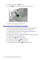
To install the processor, reverse the removal procedures.
NOTE:
After installing a new processor onto the system board, update the system ROM to ensure that
the computer using the latest version of the BIOS.
Flex card
To remove the flex card, use this procedure and illustration.
Before removing the flex card, follow these steps:
1.
Prepare the computer for disassembly (see
Preparation for disassembly
on page
20
).
2.
Remove the access panel (see
Access panel
on page
21
).
Remove the flex card:
1.
Remove two Torx screws
(1)
that secure the card to the rear of the computer.
2.
Disconnect the flex card cable from the system board connector labeled LINE OUT2
(2)
.
Flex card
51