HP Engage Flex Pro G2 Maintenance and Service Guide - Page 64
FRONT USB3, Rear expansion port see
 |
View all HP Engage Flex Pro G2 manuals
Add to My Manuals
Save this manual to your list of manuals |
Page 64 highlights
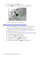
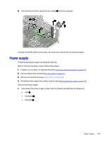
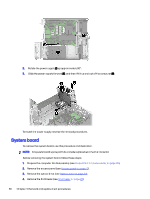
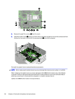
5. Rotate the drive cage to the upright position (see Rotating the drive cage on page 26). 6. Rotate the power supply to the upright position (see Rotating the power supply on page 44). 7. Remove the fan baffle (see Fan duct on page 47). When you replace the system board, be sure to remove the following components (as applicable) from the defective system board and install them on the replacement system board: ● Memory modules (see Memory modules (DIMMs) on page 27). ● Expansion cards (see Expansion cards on page 30). ● Solid-state drive (see Solid-state drive on page 38). ● WLAN module (see WLAN module on page 45). ● Heat sink (see Heat sink on page 49). ● Processor (see Processor on page 50). ● Rear expansion port (see Rear expansion port on page 53). Remove the system board: 1. Disconnect the cables from the following system board connectors: NOTE: Connected cables might vary. (1) CHFAN (2) PWRCPU (3) LINE OUT2 (4) SPKR (5) FRONT USB3 (6) PB/LED (7) SATA_PWR1 (8) PWR (9) PWRCMD (10) HDSET (11) COMB (12) SATA connectors System board 57
-
 1
1 -
2
-
3
-
4
-
5
-
6
-
7
-
8
-
9
-
10
-
11
-
12
-
13
-
14
-
15
-
16
-
17
-
18
-
19
-
20
-
21
-
22
-
23
-
24
-
25
-
26
-
27
-
28
-
29
-
30
-
31
-
32
-
33
-
34
-
35
-
36
-
37
-
38
-
39
-
40
-
41
-
42
-
43
-
44
-
45
-
46
-
47
-
48
-
49
-
50
-
51
-
52
-
53
-
54
-
55
-
56
-
57
-
58
-
 59
59 -
 60
60 -
 61
61 -
 62
62 -
 63
63 -
 64
64 -
 65
65 -
 66
66 -
 67
67 -
 68
68 -
 69
69 -
70
-
71
-
72
-
73
-
74
-
75
-
76
-
77
-
78
-
79
-
80
-
81
-
82
-
83
-
84
-
85
-
86
-
87
-
88
-
89
-
90
-
91
-
92
-
93
-
94
-
95
-
96
-
97
-
98
-
99
-
100
-
101
-
102
-
103
-
104
-
105
-
106
-
107
-
108
-
109
-
110
-
111
-
112
-
113
-
114
-
115
-
116
-
117
 |
 |
