HP LTE Notebook PC 5250 LTE 5000 Family of Personal Computers Maintenance and - Page 153
Removing and Installing the Display Assembly, left
 |
View all HP LTE Notebook PC 5250 manuals
Add to My Manuals
Save this manual to your list of manuals |
Page 153 highlights
o Clutch cradles All of these procedures require removal of the CPU cover and the display assembly. 5.8.1 Removing and Installing the Display Assembly To remove and install the display assembly, complete the following steps: 1. Prepare the computer for disassembly as described in Section 5.3. 2. Remove the CPU cover as described in Section 5.5.1. 3. Disconnect the display cables: one connector [4] and grounding lug [5] on the right, two connectors [2] [3] and one grounding lug [1] on the left (Figure 5-29). 4. Remove the two screws [1] securing the display assembly to the base assembly (Figure 5-30), and separate the display assembly from the base assembly [2].
-
 1
1 -
2
-
3
-
4
-
5
-
6
-
7
-
8
-
9
-
10
-
11
-
12
-
13
-
14
-
15
-
16
-
17
-
18
-
19
-
20
-
21
-
22
-
23
-
24
-
25
-
26
-
27
-
28
-
29
-
30
-
31
-
32
-
33
-
34
-
35
-
36
-
37
-
38
-
39
-
40
-
41
-
42
-
43
-
44
-
45
-
46
-
47
-
48
-
49
-
50
-
51
-
52
-
53
-
54
-
55
-
56
-
57
-
58
-
59
-
60
-
61
-
62
-
63
-
64
-
65
-
66
-
67
-
68
-
69
-
70
-
71
-
72
-
73
-
74
-
75
-
76
-
77
-
78
-
79
-
80
-
81
-
82
-
83
-
84
-
85
-
86
-
87
-
88
-
89
-
90
-
91
-
92
-
93
-
94
-
95
-
96
-
97
-
98
-
99
-
100
-
101
-
102
-
103
-
104
-
105
-
106
-
107
-
108
-
109
-
110
-
111
-
112
-
113
-
114
-
115
-
116
-
117
-
118
-
119
-
120
-
121
-
122
-
123
-
124
-
125
-
126
-
127
-
128
-
129
-
130
-
131
-
132
-
133
-
134
-
135
-
136
-
137
-
138
-
139
-
140
-
141
-
142
-
143
-
144
-
145
-
146
-
147
-
 148
148 -
 149
149 -
 150
150 -
 151
151 -
 152
152 -
 153
153 -
 154
154 -
 155
155 -
 156
156 -
 157
157 -
 158
158 -
159
-
160
-
161
-
162
-
163
-
164
-
165
-
166
-
167
-
168
-
169
-
170
-
171
-
172
-
173
-
174
-
175
-
176
-
177
-
178
-
179
-
180
-
181
-
182
-
183
-
184
-
185
-
186
-
187
-
188
-
189
-
190
-
191
-
192
-
193
-
194
-
195
-
196
-
197
-
198
-
199
-
200
-
201
-
202
-
203
-
204
-
205
-
206
-
207
-
208
-
209
-
210
-
211
-
212
-
213
-
214
-
215
-
216
-
217
-
218
-
219
-
220
-
221
-
222
-
223
-
224
-
225
-
226
-
227
-
228
-
229
-
230
-
231
-
232
-
233
-
234
-
235
-
236
-
237
-
238
-
239
-
240
-
241
-
242
-
243
-
244
-
245
-
246
-
247
-
248
-
249
-
250
-
251
-
252
-
253
-
254
-
255
-
256
-
257
-
258
-
259
-
260
-
261
-
262
-
263
-
264
-
265
-
266
-
267
-
268
-
269
-
270
-
271
-
272
-
273
-
274
-
275
-
276
-
277
-
278
-
279
-
280
-
281
-
282
-
283
-
284
-
285
-
286
-
287
-
288
-
289
-
290
-
291
-
292
-
293
-
294
-
295
-
296
-
297
-
298
-
299
-
300
-
301
-
302
-
303
-
304
-
305
-
306
-
307
-
308
-
309
-
310
-
311
-
312
-
313
-
314
 |
 |

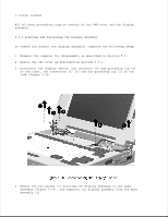
o Clutch cradles
All of these procedures require removal of the CPU cover and the display
assembly.
5.8.1 Removing and Installing the Display Assembly
To remove and install the display assembly, complete the following steps:
1. Prepare the computer for disassembly as described in Section 5.3.
2. Remove the CPU cover as described in Section 5.5.1.
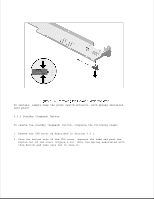
3. Disconnect the display cables: one connector [4] and grounding lug [5]
on the right, two connectors [2] [3] and one grounding lug [1] on the
left (Figure 5-29).
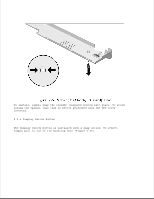
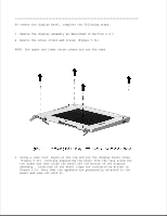
4. Remove the two screws [1] securing the display assembly to the base
assembly (Figure 5-30), and separate the display assembly from the base
assembly [2].