HP LTE Notebook PC 5250 LTE 5000 Family of Personal Computers Maintenance and - Page 172
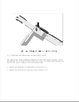
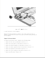
Processor Board, Remove the memory expansion board as described
 |
View all HP LTE Notebook PC 5250 manuals
Add to My Manuals
Save this manual to your list of manuals |
Page 172 highlights
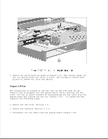
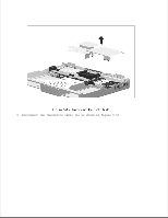
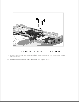
4. Lift the fan out of the computer. Reverse the above procedure to install a fan. Make certain the fan is properly oriented with the label on top and the airflow arrow pointing out of the computer. Chapter 5.11 Processor Board To remove the processor board, complete the following steps: 1. Remove the CPU cover as described in Section 5.5.1. 2. Remove the status panel as described in Section 5.6. 3. Remove the display assembly as described in Section 5.8.1. 4. Remove the memory expansion board as described in Section 5.4.6. 5. Remove the keyboard as described in Section 5.9.1. 6. Remove the clutch cradles as described in Section 5.8.6. 7. Remove the EMI shield (Figure 5-49).
-
 1
1 -
2
-
3
-
4
-
5
-
6
-
7
-
8
-
9
-
10
-
11
-
12
-
13
-
14
-
15
-
16
-
17
-
18
-
19
-
20
-
21
-
22
-
23
-
24
-
25
-
26
-
27
-
28
-
29
-
30
-
31
-
32
-
33
-
34
-
35
-
36
-
37
-
38
-
39
-
40
-
41
-
42
-
43
-
44
-
45
-
46
-
47
-
48
-
49
-
50
-
51
-
52
-
53
-
54
-
55
-
56
-
57
-
58
-
59
-
60
-
61
-
62
-
63
-
64
-
65
-
66
-
67
-
68
-
69
-
70
-
71
-
72
-
73
-
74
-
75
-
76
-
77
-
78
-
79
-
80
-
81
-
82
-
83
-
84
-
85
-
86
-
87
-
88
-
89
-
90
-
91
-
92
-
93
-
94
-
95
-
96
-
97
-
98
-
99
-
100
-
101
-
102
-
103
-
104
-
105
-
106
-
107
-
108
-
109
-
110
-
111
-
112
-
113
-
114
-
115
-
116
-
117
-
118
-
119
-
120
-
121
-
122
-
123
-
124
-
125
-
126
-
127
-
128
-
129
-
130
-
131
-
132
-
133
-
134
-
135
-
136
-
137
-
138
-
139
-
140
-
141
-
142
-
143
-
144
-
145
-
146
-
147
-
148
-
149
-
150
-
151
-
152
-
153
-
154
-
155
-
156
-
157
-
158
-
159
-
160
-
161
-
162
-
163
-
164
-
165
-
166
-
 167
167 -
 168
168 -
 169
169 -
 170
170 -
 171
171 -
 172
172 -
 173
173 -
 174
174 -
 175
175 -
 176
176 -
 177
177 -
178
-
179
-
180
-
181
-
182
-
183
-
184
-
185
-
186
-
187
-
188
-
189
-
190
-
191
-
192
-
193
-
194
-
195
-
196
-
197
-
198
-
199
-
200
-
201
-
202
-
203
-
204
-
205
-
206
-
207
-
208
-
209
-
210
-
211
-
212
-
213
-
214
-
215
-
216
-
217
-
218
-
219
-
220
-
221
-
222
-
223
-
224
-
225
-
226
-
227
-
228
-
229
-
230
-
231
-
232
-
233
-
234
-
235
-
236
-
237
-
238
-
239
-
240
-
241
-
242
-
243
-
244
-
245
-
246
-
247
-
248
-
249
-
250
-
251
-
252
-
253
-
254
-
255
-
256
-
257
-
258
-
259
-
260
-
261
-
262
-
263
-
264
-
265
-
266
-
267
-
268
-
269
-
270
-
271
-
272
-
273
-
274
-
275
-
276
-
277
-
278
-
279
-
280
-
281
-
282
-
283
-
284
-
285
-
286
-
287
-
288
-
289
-
290
-
291
-
292
-
293
-
294
-
295
-
296
-
297
-
298
-
299
-
300
-
301
-
302
-
303
-
304
-
305
-
306
-
307
-
308
-
309
-
310
-
311
-
312
-
313
-
314
 |
 |
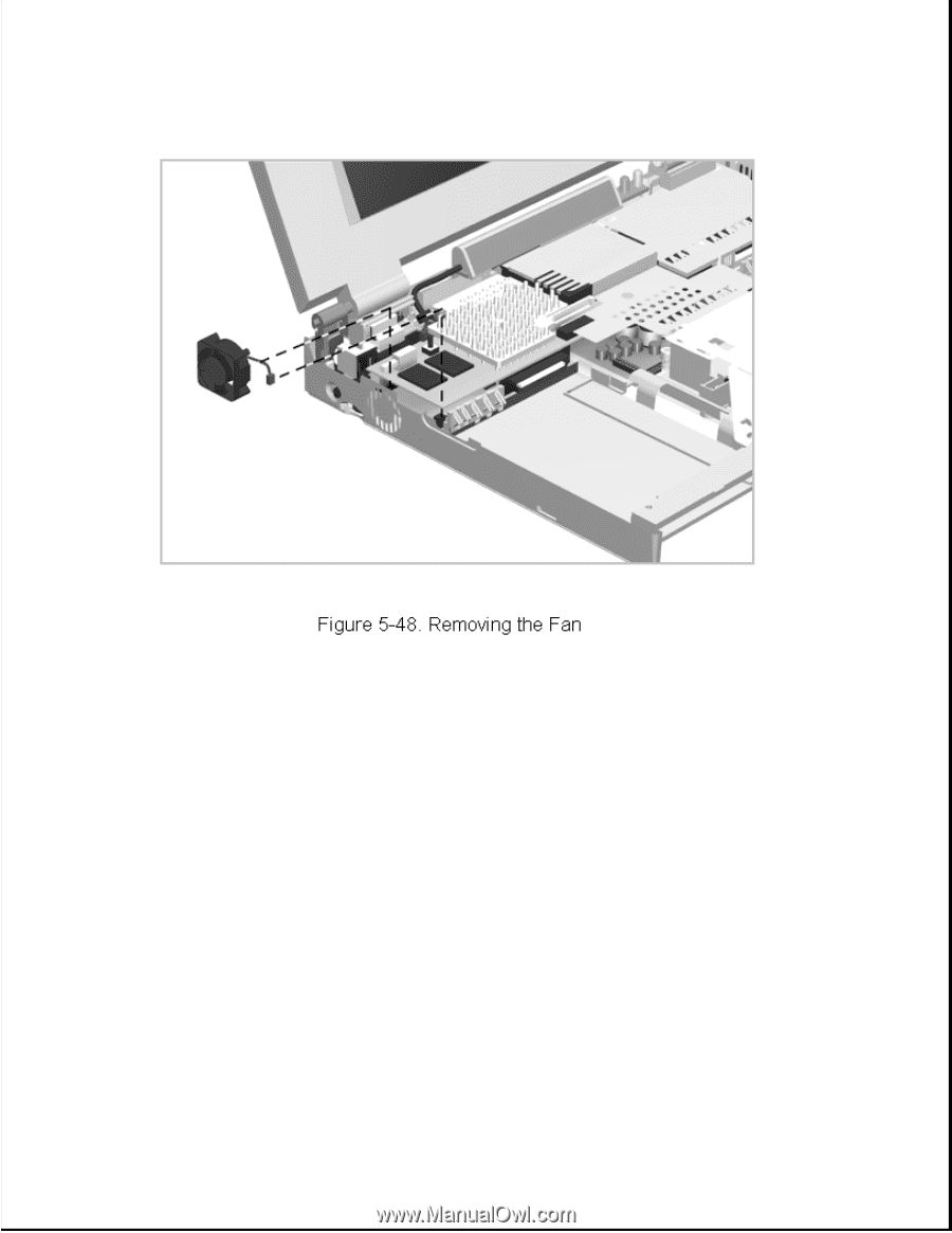
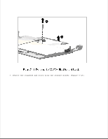
4. Lift the fan out of the computer.
Reverse the above procedure to install a fan. Make certain the fan is
properly oriented with the label on top and the airflow arrow pointing out
of the computer.
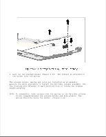
Chapter 5.11 Processor Board
To remove the processor board, complete the following steps:
1. Remove the CPU cover as described in Section 5.5.1.
2. Remove the status panel as described in Section 5.6.
3. Remove the display assembly as described in Section 5.8.1.
4. Remove the memory expansion board as described in Section 5.4.6.
5. Remove the keyboard as described in Section 5.9.1.
6. Remove the clutch cradles as described in Section 5.8.6.
7. Remove the EMI shield (Figure 5-49).