HP Mini 100e HP Mini 100e Education Edition - Maintenance and Service Guide - Page 58
and the 2 Phillips 2.0x3.0 screws
 |
View all HP Mini 100e manuals
Add to My Manuals
Save this manual to your list of manuals |
Page 58 highlights
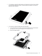
8. If it is necessary to replace the webcam module, follow these steps: a. Disconnect the webcam cable (1) from the webcam. b. Remove the Phillips 2.0x3.0 screw (2) that secures the webcam module to the display back cover. c. Remove the webcam (3). 9. If it is necessary to replace the display panel, follow these steps: a. Remove the 6 Phillips 2.5×5.0 screws (1) and the 2 Phillips 2.0x3.0 screws (2) that secure the display panel to the display back cover. b. Remove the display cable from the routing channel (3) on the back cover. 50 Chapter 4 Removal and replacement procedures
-
 1
1 -
2
-
3
-
4
-
5
-
6
-
7
-
8
-
9
-
10
-
11
-
12
-
13
-
14
-
15
-
16
-
17
-
18
-
19
-
20
-
21
-
22
-
23
-
24
-
25
-
26
-
27
-
28
-
29
-
30
-
31
-
32
-
33
-
34
-
35
-
36
-
37
-
38
-
39
-
40
-
41
-
42
-
43
-
44
-
45
-
46
-
47
-
48
-
49
-
50
-
51
-
52
-
 53
53 -
 54
54 -
 55
55 -
 56
56 -
 57
57 -
 58
58 -
 59
59 -
 60
60 -
 61
61 -
 62
62 -
 63
63 -
64
-
65
-
66
-
67
-
68
-
69
-
70
-
71
-
72
-
73
-
74
-
75
-
76
-
77
-
78
-
79
-
80
-
81
-
82
-
83
-
84
-
85
-
86
-
87
-
88
-
89
-
90
-
91
-
92
-
93
-
94
-
95
-
96
-
97
-
98
-
99
 |
 |

8.
If it is necessary to replace the webcam module, follow these steps:
a.
Disconnect the webcam cable
(1)
from the webcam.
b.
Remove the Phillips 2.0x3.0 screw
(2)
that secures the webcam module to the display back
cover.
c.
Remove the webcam
(3)
.
9.
If it is necessary to replace the display panel, follow these steps:
a.
Remove the 6 Phillips 2.5×5.0 screws
(1)
and the 2 Phillips 2.0x3.0 screws
(2)
that secure
the display panel to the display back cover.
b.
Remove the display cable from the routing channel
(3)
on the back cover.
50
Chapter 4
Removal and replacement procedures