HP Mini 5102 HP Mini 5102 - Maintenance and Service Guide - Page 61
Remove the 2 Phillips PM2.0×3.0 screws, WLAN modules are designed with a notch
 |
View all HP Mini 5102 manuals
Add to My Manuals
Save this manual to your list of manuals |
Page 61 highlights
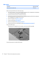
Remove the WLAN module: 1. Pull back the Mylar shield (1) from WLAN module. 2. Disconnect the wireless antenna cables (2) from the terminals on the WLAN module. 3. Remove the 2 Phillips PM2.0×3.0 screws (3) that secure the WLAN module to the system board. (The module tilts up.) 4. Remove the WLAN module (4) by pulling the module away from the slot at an angle. NOTE: WLAN modules are designed with a notch (5) to prevent incorrect insertion into the WLAN module slot. Reverse this procedure to install the WLAN module. Component replacement procedures 53
-
 1
1 -
2
-
3
-
4
-
5
-
6
-
7
-
8
-
9
-
10
-
11
-
12
-
13
-
14
-
15
-
16
-
17
-
18
-
19
-
20
-
21
-
22
-
23
-
24
-
25
-
26
-
27
-
28
-
29
-
30
-
31
-
32
-
33
-
34
-
35
-
36
-
37
-
38
-
39
-
40
-
41
-
42
-
43
-
44
-
45
-
46
-
47
-
48
-
49
-
50
-
51
-
52
-
53
-
54
-
55
-
 56
56 -
 57
57 -
 58
58 -
 59
59 -
 60
60 -
 61
61 -
 62
62 -
 63
63 -
 64
64 -
 65
65 -
 66
66 -
67
-
68
-
69
-
70
-
71
-
72
-
73
-
74
-
75
-
76
-
77
-
78
-
79
-
80
-
81
-
82
-
83
-
84
-
85
-
86
-
87
-
88
-
89
-
90
-
91
-
92
-
93
-
94
-
95
-
96
-
97
-
98
-
99
-
100
-
101
-
102
-
103
-
104
-
105
-
106
-
107
-
108
-
109
-
110
-
111
-
112
-
113
-
114
-
115
-
116
-
117
-
118
-
119
-
120
-
121
-
122
-
123
-
124
-
125
-
126
-
127
-
128
-
129
-
130
-
131
-
132
-
133
-
134
-
135
-
136
-
137
-
138
-
139
-
140
-
141
-
142
-
143
-
144
-
145
-
146
-
147
 |
 |

Remove the WLAN module:
1.
Pull back the Mylar shield
(1)
from WLAN module.
2.
Disconnect the wireless antenna cables
(2)
from the terminals on the WLAN module.
3.
Remove the 2 Phillips PM2.0×3.0 screws
(3)
that secure the WLAN module to the system board.
(The module tilts up.)
4.
Remove the WLAN module
(4)
by pulling the module away from the slot at an angle.
NOTE:
WLAN modules are designed with a notch
(5)
to prevent incorrect insertion into the WLAN
module slot.
Reverse this procedure to install the WLAN module.
Component replacement procedures
53