HP Mini 5102 HP Mini 5102 - Maintenance and Service Guide - Page 63
Top cover, Remove the 4 Torx T8 2.5×5.0 screws
 |
View all HP Mini 5102 manuals
Add to My Manuals
Save this manual to your list of manuals |
Page 63 highlights
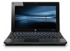
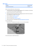
Top cover Description Top cover with TouchPad, black Top cover with TouchPad, red Top cover with TouchPad, blue Spare part number 577926-001 598461-001 598462-001 Before removing the top cover, follow these steps: 1. Shut down the device. If you are unsure whether the device is off or in Hibernation, turn the device on, and then shut it down through the operating system. 2. Disconnect all external devices connected to the device. 3. Disconnect the power from the device by first unplugging the power cord from the AC outlet and then unplugging the AC adapter from the device. 4. Remove the battery (see Battery on page 41). 5. If your device has WWAN capability, remove the SIM (see SIM on page 42). 6. Remove the memory module (see Memory module on page 43). 7. Remove the keyboard (see Keyboard on page 45). 8. Remove the hard drive or solid state drive (see Mass storage devices on page 48). 9. Remove the WLAN module (see WLAN module on page 51) Remove the top cover: 1. Turn the device upside down, with the front toward you. 2. Use a thin, flat tool to release the 4 rubber device feet. 3. Remove the 4 Torx T8 2.5×5.0 screws (1), and the 4 Phillips PM2.0×3.0 screws (2) that secure the top cover to the base enclosure. Component replacement procedures 55
-
 1
1 -
2
-
3
-
4
-
5
-
6
-
7
-
8
-
9
-
10
-
11
-
12
-
13
-
14
-
15
-
16
-
17
-
18
-
19
-
20
-
21
-
22
-
23
-
24
-
25
-
26
-
27
-
28
-
29
-
30
-
31
-
32
-
33
-
34
-
35
-
36
-
37
-
38
-
39
-
40
-
41
-
42
-
43
-
44
-
45
-
46
-
47
-
48
-
49
-
50
-
51
-
52
-
53
-
54
-
55
-
56
-
57
-
 58
58 -
 59
59 -
 60
60 -
 61
61 -
 62
62 -
 63
63 -
 64
64 -
 65
65 -
 66
66 -
 67
67 -
 68
68 -
69
-
70
-
71
-
72
-
73
-
74
-
75
-
76
-
77
-
78
-
79
-
80
-
81
-
82
-
83
-
84
-
85
-
86
-
87
-
88
-
89
-
90
-
91
-
92
-
93
-
94
-
95
-
96
-
97
-
98
-
99
-
100
-
101
-
102
-
103
-
104
-
105
-
106
-
107
-
108
-
109
-
110
-
111
-
112
-
113
-
114
-
115
-
116
-
117
-
118
-
119
-
120
-
121
-
122
-
123
-
124
-
125
-
126
-
127
-
128
-
129
-
130
-
131
-
132
-
133
-
134
-
135
-
136
-
137
-
138
-
139
-
140
-
141
-
142
-
143
-
144
-
145
-
146
-
147
 |
 |
