HP Mini 5102 HP Mini 5102 - Maintenance and Service Guide - Page 64
Phillips PM2.0×6.0
 |
View all HP Mini 5102 manuals
Add to My Manuals
Save this manual to your list of manuals |
Page 64 highlights
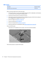
4. Turn the device right-side up, with the front toward you. 5. Open the device as far as possible. 6. Release the ZIF connector (1) that connects the button board cable to the system board. NOTE: If not done when removing the WLAN module on page 51, release any WLAN cable routed along the top cover. 7. Remove the following screws that secure the top cover to the base enclosure: ● (2) - 5 Phillips PM2.0×6.0 ● (3) - 1 Phillips PM2.0×2.5 8. Release the clips along the front edge of the top cover and open the front of the top cover (1) enough to see the TouchPad and speaker cables. 9. Lift the back edge of the top cover up and forward (2) to release the clips along the rear edge of the top cover. 56 Chapter 4 Removal and replacement procedures
-
 1
1 -
2
-
3
-
4
-
5
-
6
-
7
-
8
-
9
-
10
-
11
-
12
-
13
-
14
-
15
-
16
-
17
-
18
-
19
-
20
-
21
-
22
-
23
-
24
-
25
-
26
-
27
-
28
-
29
-
30
-
31
-
32
-
33
-
34
-
35
-
36
-
37
-
38
-
39
-
40
-
41
-
42
-
43
-
44
-
45
-
46
-
47
-
48
-
49
-
50
-
51
-
52
-
53
-
54
-
55
-
56
-
57
-
58
-
 59
59 -
 60
60 -
 61
61 -
 62
62 -
 63
63 -
 64
64 -
 65
65 -
 66
66 -
 67
67 -
 68
68 -
 69
69 -
70
-
71
-
72
-
73
-
74
-
75
-
76
-
77
-
78
-
79
-
80
-
81
-
82
-
83
-
84
-
85
-
86
-
87
-
88
-
89
-
90
-
91
-
92
-
93
-
94
-
95
-
96
-
97
-
98
-
99
-
100
-
101
-
102
-
103
-
104
-
105
-
106
-
107
-
108
-
109
-
110
-
111
-
112
-
113
-
114
-
115
-
116
-
117
-
118
-
119
-
120
-
121
-
122
-
123
-
124
-
125
-
126
-
127
-
128
-
129
-
130
-
131
-
132
-
133
-
134
-
135
-
136
-
137
-
138
-
139
-
140
-
141
-
142
-
143
-
144
-
145
-
146
-
147
 |
 |
