HP Pavilion 11-h110nr HP Pavilion 11 x2 PC Maintenance and Service Guide - Page 81
Release the hinge assembly HDMI side cable and Audio side cable from the retention clips
 |
View all HP Pavilion 11-h110nr manuals
Add to My Manuals
Save this manual to your list of manuals |
Page 81 highlights
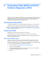
4. Remove the bottom cover (see Bottom cover on page 61). 5. Disconnect the keyboard base battery cable from the docking board (see Keyboard base battery on page 62). Remove the hinge assembly: 1. Disconnect the following cables: (1) Hinge assembly "HDMI side" cable from the HDMI/USB board (2) and (3) Hinge assembly cables from the docking board (4) Hinge assembly "Audio side" cable from the audio/USB board 2. Release the hinge assembly "HDMI side" cable and "Audio side" cable from the retention clips (5) built into the hinges. 3. Remove the two Phillips PM1.85×5.50 screws (1) that secure the hinge assembly to the keyboard/top cover. Keyboard base component replacement procedures 73
-
 1
1 -
2
-
3
-
4
-
5
-
6
-
7
-
8
-
9
-
10
-
11
-
12
-
13
-
14
-
15
-
16
-
17
-
18
-
19
-
20
-
21
-
22
-
23
-
24
-
25
-
26
-
27
-
28
-
29
-
30
-
31
-
32
-
33
-
34
-
35
-
36
-
37
-
38
-
39
-
40
-
41
-
42
-
43
-
44
-
45
-
46
-
47
-
48
-
49
-
50
-
51
-
52
-
53
-
54
-
55
-
56
-
57
-
58
-
59
-
60
-
61
-
62
-
63
-
64
-
65
-
66
-
67
-
68
-
69
-
70
-
71
-
72
-
73
-
74
-
75
-
 76
76 -
 77
77 -
 78
78 -
 79
79 -
 80
80 -
 81
81 -
 82
82 -
 83
83 -
 84
84 -
 85
85 -
 86
86 -
87
-
88
-
89
-
90
-
91
-
92
-
93
-
94
-
95
-
96
-
97
-
98
-
99
-
100
 |
 |

4.
Remove the bottom cover (see
Bottom cover
on page
61
).
5.
Disconnect the keyboard base battery cable from the docking board (see
Keyboard base battery
on page
62
).
Remove the hinge assembly:
1.
Disconnect the following cables:
(1)
Hinge assembly “HDMI side” cable from the HDMI/USB board
(2)
and
(3)
Hinge assembly cables from the docking board
(4)
Hinge assembly “Audio side” cable from the audio/USB board
2.
Release the hinge assembly “HDMI side” cable and “Audio side” cable from the retention clips
(5)
built into the hinges.
3.
Remove the two Phillips PM1.85×5.50 screws
(1)
that secure the hinge assembly to the
keyboard/top cover.
Keyboard base component replacement procedures
73